


MC97F6108A User’s manual
18. Reset
195
18.5
Brown out detector processor
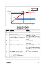
MC97F6108A has an On-chip brown-out detection circuit (BOD) for monitoring VDD level during
operation by comparing it to a fixed trigger level. Trigger level for the BOD can be selected by
configuring BODLS[2:0] bits to be 2.2V, 2.5V, 2.7V, 3.2V, 3.7V, 4.2V.
In the STOP mode, this will contribute significantly to the total current consumption. So to minimize the
current consumption, select BODLS[2:0] to 000b to disable BOD by software.
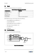
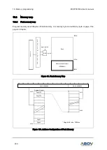
Figure 95. BOD Block Diagram
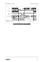
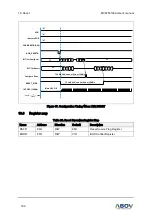
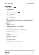
Figure 96. Internal Reset at Power Fail Situation
BODLS[1:0]
RESET_BODB
Brown Out
Detector
(BOD)
D Q
CP
r
D Q
CP
r
DE-BOUNCE
CLK
External VDD
BODEN
BODRF
(BOD Reset Flag)
CPU
Write
SCLK
(System CLK)
nPOR
STOP_MODE
0
1
VDD
Internal
RESETB
VDD
Internal
RESETB
V
BOD
MAX
V
BOD
MIN
8ms at 16MHz
t < 8ms at 16MHz
8ms at 16MHz
V
BOD
MAX
V
BOD
MIN