


MC97F6108A User’s manual
17. Power down operation
185
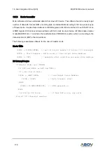
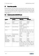
17.2
IDLE mode
P
ower control register is set to ‘01h’ to enter
into IDLE mode. In IDLE mode, internal oscillation circuits
remain active. Oscillation continues and peripherals are operated normally, but CPU stops.
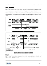
It is released by reset or an interrupt. To be released by an interrupt, the interrupt should be enabled
before IDLE mode. If using a reset, because the device is initialized, registers become to have reset
values.
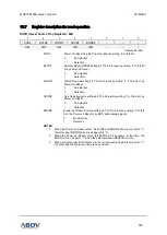
Figure 82. IDLE Mode Release Timing by an External Interrupt
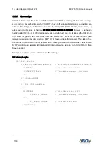
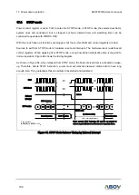
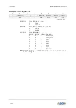
Figure 83. IDLE Mode Release Timing by an RESETB
Example
MOV
PCON, #0000_0001b ; The Setting of IDLE mode, Set the bit of STOP and
IDLE Control register (PCON)
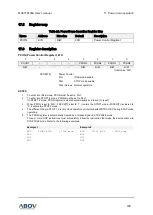
External
Interrupt
OSC
Normal Operation
Release
CPU Clock
Stand-by Mode
Normal Operation
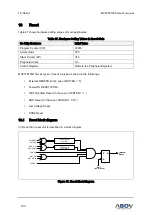
OSC
CPU Clock
RESETB
Normal Operation
BIT Counter
IDLE Mode
Normal Operation
Release
Set PCON
to 01
Clear & Start
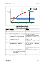
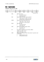
TST = 32.7ms @ 16MHz
𝐓𝐒𝐓 =
𝟏
𝐟𝐎𝐒𝐂
× 𝟐𝟎𝟒𝟖 × 𝟐𝟓𝟔
m-2
m-1
m
n
0
0
0
1
FD
FE
FF
0
1
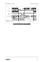
T
OSC
= 1/f
OSC
f
OSC
= 16MHz
BCK[1:0] in BCCR = 00
B
BPD[2:0] in BCCR = 111
B
2048 T
OSC