


A96G140/A96G148/A96A148 User’s manual
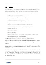
16. USART 2
205
In master mode of operation, even if transmission is not enabled (TXE=0), writing data to UDATA
register is necessary because the clock XCK is generated from a transmitter block.
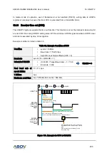
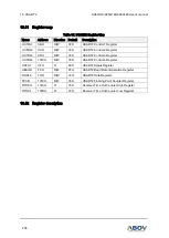
16.10
Receiver time out (RTO)
This USART2 system supports the time out function. This function is occur the interrupts when stop bit
are not in RX line during URTOC setting value. RTO count stops in RXD signal live state and RTO clear
and start is executed by stop bit recognition.
Example condition is listed in table 35.
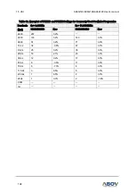
Table 36. Example Condition of RTO
Condition
sysclk = 16MHz
Baud rate = 115,200 bps
Asynchronous Normal Mode (U2X = 0)
Baud rate
sysclk / 16 x (UBAUD + 1)
Calculated UBAUD
(1000000 / Target Baud rate)
–
1 = 7.68
Error rate = 0.68
UBAUD = 8
Real baud rate at
sysclk 16Mhz
111,111 bps
1 bit time
9us
Maximum count time 9us * 65536(16bit count) = 589.8ms
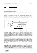
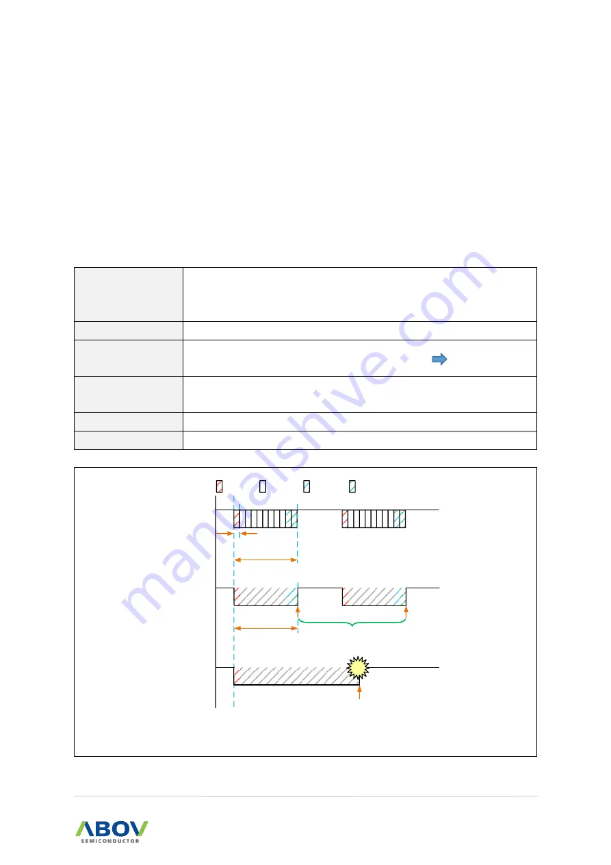
USART RX
Start bit
Data bit
Parity bit
Stop bit
1 bit time
= 9us (@111111 bps)
1 Frame t ime (parity, 1 Stop)
= 99us (@111111 bps)
A96G140
USART RX
Data 0x00
Case1
RTO count stops in RXD signal Live state.
Even if it is set smaller than frame time, it does not count..
RTO Clear&Start is executed by stop bit
A96G140
USART RX
Frame Error
Case2
If a disconnect problem occurs , interrupt is
Generated af ter the internal buffer 2 data is
filled.
Frame error can be checked by Frame
Error State Flag.
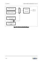
Figure 110. Example for RTO in USART2