


15. USI
A96G140/A96G148/A96A148 User’s manual
182
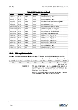
Table 31. USI Register Map (continued)
Name
Address
Direction
Default
Description
USI0ST1
E1H
R/W
80H
USI0 Status Register 1
USI0ST2
E2H
R
00H
USI0 Status Register 2
USI1BD
F3H
R/W
FFH
USI1 Baud Rate Generation Register
USI1DR
F5H
R/W
00H
USI1 Data Register
USI1SDHR F4H
R/W
01H
USI1 SDA Hold Time Register
USI1SCHR F7H
R/W
3FH
USI1 SCL High Period Register
USI1SCLR F6H
R/W
3FH
USI1 SCL Low Period Register
USI1SAR
EDH
R/W
00H
USI1 Slave Address Register
USI1CR1
E9H
R/W
00H
USI1 Control Register 1
USI1CR2
EAH
R/W
00H
USI1 Control Register 2
USI1CR3
EBH
R/W
00H
USI1 Control Register 3
USI1CR4
ECH
R/W
00H
USI1 Control Register 4
USI1ST1
F1H
R/W
80H
USI1 Status Register 1
USI1ST2
F2H
R
00H
USI1 Status Register 2
15.22
USIn register description
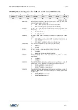
USInBD (USIn Baud- Rate Generation Register: For UART and SPI mode): E3H/F3H, n = 0, 1
7
6
5
4
3
2
1
0
USInBD7
USInBD 6
USInBD 5
USInBD 4
USInBD 3
USInBD 2
USInBD 1
USInBD 0
R/W
R/W
R/W
R/W
R/W
R/W
R/W
R/W
Initial value: FFH
USInBD[7:0]
The value in this register is used to generate internal baud rate in
asynchronous mode or to generate SCKn clock in SPI mode. To
prevent malfunction, do not write
‘0’ in asynchronous mode and do
not write
‘0’ or ‘1’ in SPI mode.
NOTE:
In common with USInSAR register, USInBD register is used
for slave address register when the USIn I2C mode.