


EN - 12
BAL.0022 • 2019-04-23
6 Operation
Alignment jig
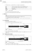
The measuring sleeves are torch-specific and have different threaded stems:
1
Screw in the measuring sleeve at the position of the contact tip.
2
Plug on/screw in the adjusting sleeve at the position of the gas nozzle.
6 Operation
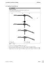
6.1 Quick Control
1
Remove the neck liner and the wire guide.
2
Fasten the change neck torch into the clamping device.
3
Move the test madrel
to the contact tip
The bending angle is correct if the tip of the test mandrel
and the contact tip
are centered.
6.1.1 Check the alignment.
1
Unscrew or pull out the gas nozzle and remove other torch-specific fittings.
2
at the position of the contact tip.
The bending angle is correct if the test mandrel
fits easily into the bore of the measuring sleeve
.
M8
WH 455, WH 505/505 TS, ROBO VTS 0/500 TS,
ABIROB
®
W 500 TS
M6
WH 241/242, ROBO VTS 500/500 TS, ROBO VTS 290, ABITIG-WH
M10
WH 650/652
M10x1
ABIROB
®
350 GC
Tab. 7
Adjusting sleeves
NOTICE
Before inserting the torch into the alignment jig, check:
• Whether the correct interface and the corresponding torch are inserted.
• Whether the dust and welding spatters are removed. This might cause wear and reduced test accuracy.
1
Test mandrel
2
Contact tip
Abb. 8
Quick Control
2
1
1
Test mandrel
2
Measuring sleeve
Abb. 9
Checking the Alignment
2
1


