ABB ZGP2 Series Operating Instructions Manual Download Page 3

1

CONTENTS

1

INTRODUCTION

Section

Page

1

INTRODUCTION .............................................................. 1

2

PREPARATION ................................................................ 2

2.1

Unpacking ............................................................... 2

2.2

Checking the Code Number .................................... 2

2.3

Assembling the Probe ............................................. 2

3

INSTALLATION ................................................................ 4

3.1

Types of Measuring Systems .................................. 4

3.2

Siting ....................................................................... 6

3.3

Mounting .................................................................. 8
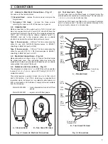
4

CONNECTIONS ............................................................... 9

4.1

Access to Electrical Connections ............................ 9

4.2

Cable Details ........................................................... 9

4.3

Electrical Connections ............................................. 9

4.4

Reference Air Connections ...................................... 9

4.5

Test Gas Inlet .......................................................... 9

5

OPERATION .................................................................. 10

5.1

Principles of Operation .......................................... 10

5.2

Range of Operation ............................................... 10

6

MAINTENANCE ............................................................. 10
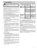
7

FAULT FINDING ............................................................ 11

7.1

In Situ Checking Using a Test Gas ........................ 11
7.1.1

Standard Head ......................................... 11

7.1.2

Twin Gland C95 Head .............................. 11

7.2

Comparison with Another O2 Probe ...................... 11

7.3

Returning the Probe to the
Factory for Checking ............................................. 11

7.4

Continuity Check ................................................... 11

8

SPECIFICATION ............................................................ 12

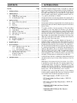
The ZGP2 Zirconia Oxygen Probe is designed to measure
oxygen in oxidising, and some reducing, furnace atmospheres.
When used in conjunction with an appropriate electronics unit
the probe output voltage may be converted to a signal related
either to oxygen concentration, or oxidising potential, terms i.e.
%O

2

, ppmO

2

, kilocalories or millivolts.

Concentration terms are usually applicable to measurements in
oxidising atmospheres and potential terms are used for reducing
atmospheres.

Atmospheres which are strongly reduced, and which may have
free carbon present, are best monitored using the Z-CS2 Carbon
Sensor Probe.

The probe provides a true measurement of the atmospheric
conditions in situ and permits continuous and accurate
measurement over a wide temperature range without frequent
maintenance associated with external sampling systems. It also
eliminates ‘equilibrium shift’, common to other systems in which
gas samples are cooled before measurement, and has a fast
response to changes in atmosphere, enabling rapid corrective
action to be taken when necessary.

The probe comprises a ceramic detector cell housed in a
protective sheath. A thermocouple is fitted within the probe to
enable the process temperature to be monitored or for automatic
temperature compensation to be provided – see Section 5.1.
The sheath material is either aluminous porcelain (recommended
for oxidising atmospheres) or Incoloy 800 (recommended for
reducing atmospheres) for use at maximum temperatures of
1250

°

C (2282

°

F) and 1000

°

C (1832

°

F) respectively. Special

sheaths are available for use up to 1400

°

C (2552

°

F). A connector

head (protected to IP54 or IP56) facilitates connection of the
cell output, thermocouple and reference air connections.

A calibration gas inlet port is provided to enable the probe to be
checked using test gas mixtures without removing it from the
process.

Reference air, at a volume of 500 to 1000 ml/min. (1 to 2 ft

3

/hr),

is required for accurate operation. This can be supplied from a
mains-powered pump unit (Part No. 003000240) or a flow
regulator unit (Part No. 003000241), full details of which are
included in the Operating Instructions: Zirconia Reference Air
Supply Units – Part No. 003000239, Issue 1 onwards.

The ZGP2 probe can be operated with any of the following
instrumentation supplied by the Company, full details of which
are included in their respective Operating Instructions:

Z-MT Oxygen Analyzer


– IM/ZMT, Issue 5 or later

ZDT Oxygen Analyzer (Low Temp. Version)


– IM/ZDT/FG,

Issue 4 or later

ZDT Oxygen Analyzer (High Temp. Version)


– IM/ZDT/GP,

Issue 3 or later

COMMANDER SR100A Advanced Process Recorder

– IM/SR100APAK.

COMMANDER SR100B Multipoint Chart Recorder

– IM/SR100BPAK.

Summary of Contents for ZGP2 Series

Page 1: ...AnalyzeIT High Temperature Zirconia Oxygen Probe ZGP2 Series Operating Instructions IM ZGP2_8 ...

Page 2: ...l conditions result in degraded process system performance leading to personal injury or death Therefore comply fully with all Warning and Caution notices Information in this manual is intended only to assist our customers in the efficient operation of our equipment Use of this manual for any other purpose is specifically prohibited and its contents are not to be reproduced in full or part without...

Page 3: ...librium shift common to other systems in which gas samples are cooled before measurement and has a fast response to changes in atmosphere enabling rapid corrective action to be taken when necessary The probe comprises a ceramic detector cell housed in a protective sheath A thermocouple is fitted within the probe to enabletheprocesstemperaturetobemonitoredorforautomatic temperature compensation to ...

Page 4: ...h is fitted adjust the diameter of the wadding at the end of the probe to allow a snug fit To reduce its diameter the wadding may be compressed slightly To increase its diameter apply slight end pressure on the wire bonding at both ends of the wadding Mould the wadding by hand to ensure a light push fit into the sheath 2 2 Checking the Code Number Ensure that the correct equipment is being install...

Page 5: ...3 Wadding Filter Washer Vent Holes 1 to 1 5 mm 1 3 2 5 6 7 8 8 3 4 5 8 2 2 PREPARATION Fig 2 1 Assembling the Probe ...

Page 6: ...urement is required i e O2 ppmO2 or O2 partial pressure temperature compensation of the probe output is usually necessary If the process temperature is constant or if variations in operating temperature do not produce unacceptable errors as in some flue gas measurement it is possible to measure O2 concentration without temperature compensation using a system similar to that for oxygen potential Sy...

Page 7: ...uple mV Output from Zirconia Cell Thermocouple Output from Probe Z MT Oxygen Analyzer Alarm Control or Retransmission Outputs Alarm Control or Retransmission Outputs Alarm Control Retransmission or Serial Data Output Power Supply Remote Fuel Selector dual fuel versions only Carbon Monoxide Monitor 3 INSTALLATION Fig 3 2 Oxygen Concentration Measurement using Basic Oxygen Analyzer Fig 3 3 Oxygen Co...

Page 8: ... subsequent removal Dimensions for the probe are shown in Figs 3 4 to 3 6 A clearance of at least 25mm in excess of the overall probe length is necessary for installation or removal procedures Caution The probe MUST NOT be sited a where it is subjected to mechanical or thermal shock b in the presence of aggressive components e g molten slags molten silicates metals and vapours of lead zinc silicon...

Page 9: ...ustomer M16 Cable Entries x2 Reference Air Line Entry Mounting Flange Probe Outer Sheath Test Gas All dimensions in mm inches 3 INSTALLATION 3 2 Siting Figs 3 4 to 3 6 Fig 3 5 Overall Dimensions Twin Gland C95 Head Fig 3 6 Overall Dimensions 1 in NPT Adaptor 69 8 2 74 View A A 15 0 59 Twin Gland Head Shown for Information Only All dimensions in mm inches ...

Page 10: ...e of the probe including any stand off which may be used is thermally insulated to minimize condensation within the probe see Fig 3 7 Condensation within the probe sheath particularly in outdoor installations can be sufficient to allow water to come into contact with the hot ceramic zirconia tube leading to thermal shock and failure of the sensor This problem is most likely to occur on such instal...

Page 11: ...able for use with Pt Pt 13 Rh thermocouples to BS4937 sheathing to BS6746 part no E37 4 3 Electrical Connections Fig 4 2 Make connections as shown in Fig 4 2 and on the label inside the probe head cover The connecting cable must enter the probe head via the bush provided standard head or suitable cable glands twin gland C95 head 4 4 Reference Air Connections Fig 4 2 The reference air connector is ...

Page 12: ...ference Gas P1 Partial Pressure Sample Gas C Cell Constant For oxygen potential measurement the following two expressions relate the oxygen probe output E mV to oxygen potential µ E 10 84µ 40 where µ is in kilocalories or E 2 591µ 40 where µ is in kilojoules 5 2 Range of Operation Fig 5 1 The internal resistance of the cell i e the resistance of the electrolyte between the electrodes decreases app...

Page 13: ...nnections b Remove the screwed plug from the test gas connector see Fig 4 2A c Fit 1 4in i d x 3 8in o d plastic or similar tubing and supply a test gas of known oxygen concentration to the probe at a steady flow rate of 800 to 1000ml min 1 7 to 2 1ft3 hr Allow at least 5 minutes for the system to stabilize before making a measurement d Check that the oxygen concentration measured by the probe sys...

Page 14: ...he limits are given in Table 8 1 for 1 electronic conduction but in practice it may be possible to measure even lower oxygen potential levels without introducing significant errors Electrical Data Cell Constant 0V 2mV Probe accuracy Typically better than 5 of reading System accuracy 2 of test gas reading when calibrated against a certified test gas Cell output impedance Typically 100kΩ 700 C 1292 ...

Page 15: ...umentation pH conductivity and dissolved oxygen transmitters and sensors ammonia nitrate phosphate silica sodium chloride fluoride dissolved oxygen and hydrazine analyzers Zirconia oxygen analyzers katharometers hydrogen purity and purge gas monitors thermal conductivity Customer Support We provide a comprehensive after sales service via a Worldwide Service Organization Contact one of the followin...

Page 16: ... Lockheed Way Carson City NV 89706 USA Tel 1 775 883 4366 Fax 1 775 883 4373 ABB has Sales Customer Support expertise in over 100 countries worldwide www abb com The Company s policy is one of continuous product improvement and the right is reserved to modify the information contained herein without notice Printed in UK 03 04 ABB 2004 ...

Reviews: