


Appendix H Tools
Conventional maintenance tools are generally all that is necessary to perform installation
and basic measurements for diagnostic purposes. A suitable “allen” wrench is needed
to remove the cover looking screw.
Anti-ESD wrist strap is needed when operating with the rear cover removed.
This section is intended to describe the tools needed to install and service the SF910i
product itself, not considering the mechanical tools, welding station, and accessories
that are needed to physically mount the fiber optic external guide pipe, flanges and
generically speaking all mounting accessories (among them: purge air pipe, swivel
flange, valves, and so on).
H.1
Tools
–
Allen wrench (2mm) for the cover locking screw
–
Allen wrench (3mm) for unlocking the quick-release connector
–
Only for SF910i-XX-XX-QC-type
–
One small flat-blade screwdriver (2÷2.5mm) for the removable terminal screws
–
One medium/large flat-blade screwdriver (5mm) for the earth connection screw
–
Cutter
–
Anti-ESD wrist strap or other equivalent system
–
DMM (not strictly mandatory; could be useful to check the wiring of power supply,
digital inputs, and analog output 4÷20mA)
–
Silicone grease (to add to the rear cover thread before reinstalling it). A copper-based
lubricating paste can be used, for instance, Product code 8160 from AREXONS,
MISAL AREXONS SpA, Via Antica di Cassano, 23, Cernusco S/N (MI) Italy, Phone:
(+39) 02 924361
8VZZ005286 B
181
H Tools
H.1 Tools
Summary of Contents for Uvisor SF910i
Page 2: ......
Page 6: ......
Page 20: ...8VZZ005286 B 20...
Page 30: ...8VZZ005286 B 30...
Page 68: ...8VZZ005286 B 68...
Page 78: ...8VZZ005286 B 78...
Page 90: ...8VZZ005286 B 90...
Page 92: ...8VZZ005286 B 92...
Page 98: ...8VZZ005286 B 98...
Page 108: ...8VZZ005286 B 108...
Page 114: ...8VZZ005286 B 114...
Page 118: ...8VZZ005286 B 118...
Page 126: ...8VZZ005286 B 126...
Page 128: ...8VZZ005286 B 128...
Page 130: ...8VZZ005286 B 130...
Page 150: ...8VZZ005286 B 150...
Page 151: ...Appendix E Drawings 8VZZ005286 B 151 E Drawings...
Page 152: ...Figure E 1 Enclosure Quick Release Connector and Version LOS 8VZZ005286 B 152 E Drawings...
Page 153: ...Figure E 2 Enclosure NPT Cable Inlet and Version LOS 8VZZ005286 B 153 E Drawings...
Page 154: ...Figure E 3 Enclosure Quick Release Connector and Version FOC 8VZZ005286 B 154 E Drawings...
Page 155: ...Figure E 4 Enclosure NPT Cable Inlet and Version FOC 8VZZ005286 B 155 E Drawings...
Page 156: ...Figure E 5 FOC Flexible Assembly 8VZZ005286 B 156 E Drawings...
Page 157: ...Figure E 6 FOC Rigid Assembly 8VZZ005286 B 157 E Drawings...
Page 160: ...Figure E 9 Bailey Flame ON Standard Replacement 8VZZ005286 B 160 E Drawings...
Page 161: ...Figure E 10 Typical Bailey Flame ON Installation 8VZZ005286 B 161 E Drawings...
Page 162: ...8VZZ005286 B 162...
Page 170: ...8VZZ005286 B 170...
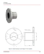
Page 178: ...G 7 Counter Flange 8VZZ005286 B 178 G Fittings G 7 Counter Flange...
Page 189: ......


