


Electrical connection
18 - EN
TTH200
CI/TTH200-EN
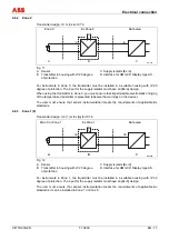
4.6.4 Zone 1 (20)
Transmitter design: II 2 G (1D) Ex [iaD] ib IIC T6
Zone 0, Zone 1,
Zone 20
Ex Zone 1
Safe area
ib
B
C
ib
A00147
ia
J
A
D
i
a
Fig. 13
A Sensor
B Transmitter in housing with IP 20 degree
of protection
C Supply isolator [Ex ib]
D Interface for HMI LCD Display type AS
For instruments in Zone 1, the transmitter must be installed in a suitable housing with IP 20
degree of protection. The input for the supply isolator must have an [Ex ib] design.
The user must ensure that sensor instrumentation meets the requirements of applicable Ex
standards. It can be installed in Zone 0, Zone 1, or Zone 20.
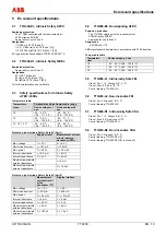
4.6.5 Zone
2
Transmitter design: II 3 G Ex nA II T6
Ex Zone 2
Safe area
B
C
A00148
J
A
D
Fig. 14
A Sensor
B Transmitter in housing with IP 54 degree
of protection
C Supply isolator
D Interface for HMI LCD Display type AS
For instruments in Zone 2, the transmitter must be installed in a suitable housing with a degree
of protection of at least IP 54.
In the event of a disturbance, it must be ensured that the supply voltage cannot exceed the
normal voltage by more than 40 %.


