Advanced Videographic Recorder
SM2000
4 CONFIGURATION
IM/SM2000
Issue 11
81
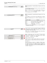
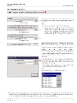
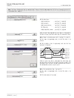
Set the required electrical range.
Notes.
Applicable only to mA, mV, V and Resistance input types.
When an input is connected through an external voltage
divider (see
Warnings
on page 80), set the electrical range
low and high values to the actual voltage applied to the
divider, not the voltage after it has been divided down. The
range of the electrical input signal is determined by the
input type – see Table 4.3:
Input
Standard Inputs
High Specification Inputs
Type
mV
V
mA
Ω
mV
V
mA
Ω
Min.
0
0
0
0
–1000
–50
–100
0
Max.
2000
20
50
5000
1000
50
100
2000
Table 4.3 Limits of Electrical Ranges
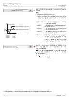
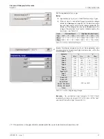
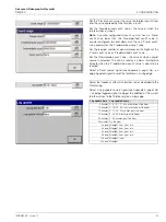
Specify the display range and units of the engineering value
corresponding to the electrical high and low values, within the
limits defined in Table 4.4:
1
THC/RTD
°C
°F
Type
Min.
Max.
Min.
Max.
Type B
–18
1800
0
3270
Type E
–100
900
–140
1650
Type J
–100
900
–140
1650
Type K
–100
1300
–140
2350
Type L
–100
900
–140
1650
Type N
–200
1300
–325
2350
Type R & S
–18
1700
0
3090
Type T
–250
300
–400
570
Pt100
–200
600
–325
1100
Power 5/2
–999 to +9999
Power 3/2
Square Root
Custom Linearizer 1
Custom Linearizer 2
Linear
Table 4.4 Limits of Engineering Ranges
Example
– for an electrical input range of 4.0 to 20.0mA,
representing a pressure range of 50 to 250 bar, set the 'Low'
value to 50.0 and the 'High' value to 250.0.
•1
If this parameter is changed, internally recorded data files are recreated and unarchived data is lost.


