Operating Instruction
42/14-37-EN
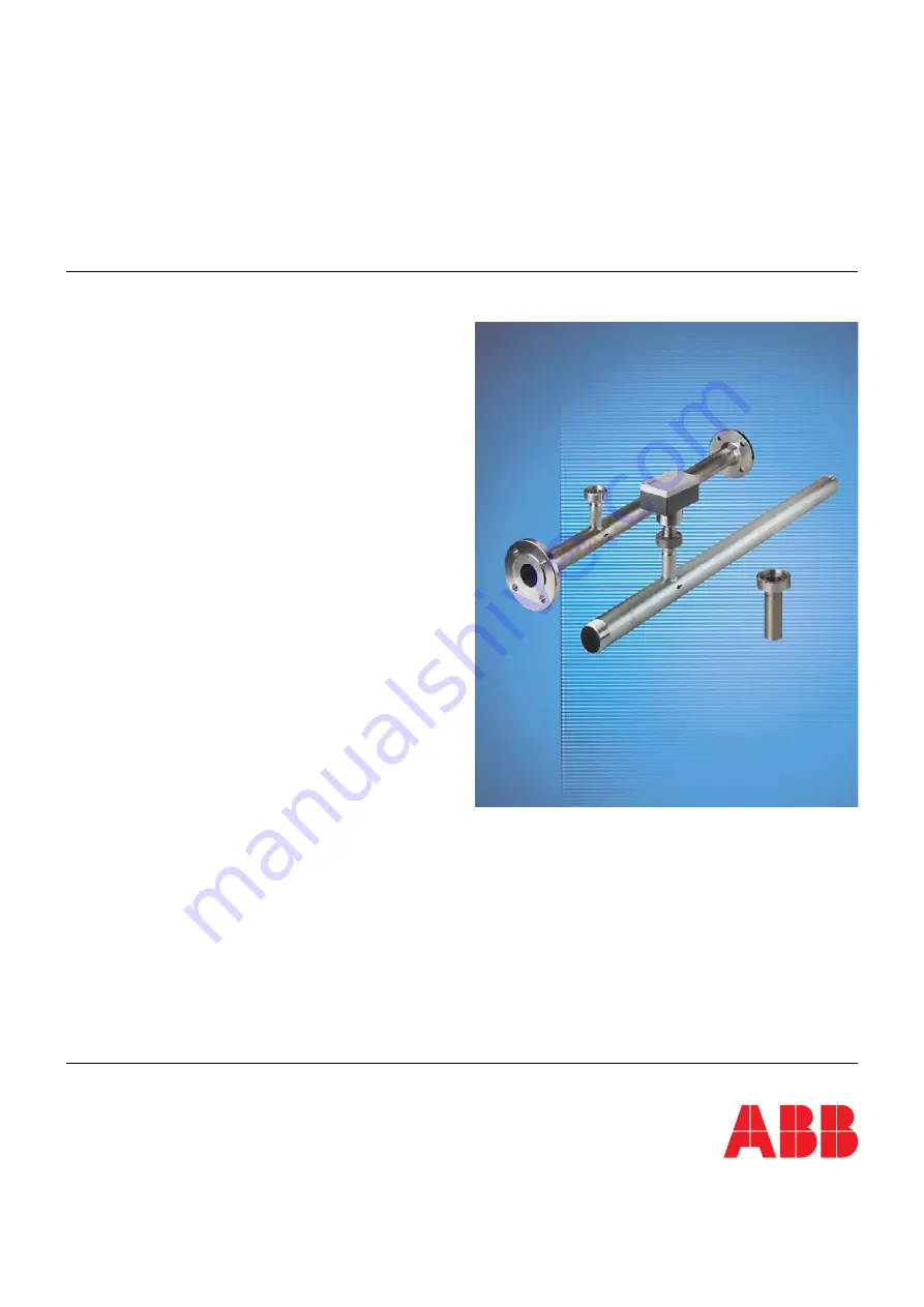
Thermal Mass Flowmeter
Sensyflow FMT200-D
for biogas and compressed air applications
Page 1: ...Operating Instruction 42 14 37 EN Thermal Mass Flowmeter Sensyflow FMT200 D for biogas and compressed air applications...
Page 2: ...551 905 534 Fax 49 551 905 555 Customer service center Phone 49 180 5 222 580 Fax 49 621 381 931 29031 automation service de abb com Copyright 2010 by ABB Automation Products GmbH Subject to changes w...
Page 3: ...nd Electronic Equipment 10 1 10 2 RoHS Directive 2002 95 EC 10 2 Design and function 11 2 1 Pipe components 12 2 2 Flowmeter sensor 12 3 Mounting 13 3 1 Recommended steadying lengths according to DIN...
Page 4: ...ual must be observed and followed in order to maintain this state throughout the period of operation Modifications and repairs to the product may only be performed if expressly permitted by these inst...
Page 5: ...carried out on the entire system The materials used must be checked by the user to ensure their suitability for the application concerned The maximum operating conditions relating to pressure and tem...
Page 6: ...ed not a flat gasket This is resistant to measuring media and should be inserted in the groove provided in the pipe component flange Take care not to damage the measuring elements when inserting the f...
Page 7: ...may result in death or severe injury WARNING Bodily injury This symbol in conjunction with the signal word Warning indicates a potential electrical hazard Failure to observe this safety information m...
Page 8: ...lation The electrical connection may only be made by authorized specialist personnel according to the electrical plans The electrical connection information in the manual must be observed otherwise th...
Page 9: ...s incurred as a result of the device not having been adequately cleaned or of any failure to dispose of hazardous materials The manufacturer reserves the right to return a contaminated device Please P...
Page 10: ...cept and dispose of returns for a fee 1 10 2 RoHS Directive 2002 95 EC With the Electrical and Electronic Equipment Act ElektroG in Germany the European Directives 2002 96 EC WEEE and 2002 95 EC RoHS...
Page 11: ...it is possible to directly determine the mass flow rate This means there is no need for pressure and temperature influences to be compensated The calibration of the devices is done on a highly precise...
Page 12: ...ersions available as standard depending on the respective nominal diameter and the desired adaptation are shown in chapter 8 Specifications 2 2 Flowmeter sensor The flowmeter sensor designed as a plug...
Page 13: ...ombinations of inlet run dist urbances e g valve and reducer you must always consider the longer inlet run length In confined spaces at the mounting location the outlet run length can be shortened to...
Page 14: ...utflow sections Correctly mount the flowmeter sensor to the pipe component Correctly install all gaskets and check them for perfect condition Correctly install all electrical connections 3 3 Selecting...
Page 15: ...skets used must not alter the cross section of the opening in the pipeline and must ensure complete tightness once the flowmeter sensor and pipe component have been installed The centering pin on the...
Page 16: ...wall thickness of the pipe in mm when ordering 34 1 34 D H1 Rd52 x 1 6 L 1 G01022 Flow direction Fig 4 Weld on adapter DIN 11851 with lock nut Dimensions in mm inch 1 Centering pin Important Always mo...
Page 17: ...Mounting 42 14 37 EN Sensyflow FMT200 D 17 G01036 Centering pin Flow direction Fig 5 Weld on adapter mounted to pipeline centering pin right outflow side...
Page 18: ...able entry 1 A shielded four core cable e g 4 x 1 mm2 must be used to connect the flowmeter sensor 2 Release the four screws on the connection head cover of the flowmeter sensor and remove the cover 3...
Page 19: ...can result in severe injuries or death Important Notice In the case of 24 V UC supply power the device may only be supplied with a safely isolated low voltage DIN VDE 0106 Under no circumstances must...
Page 20: ...mA or maximum greater than 22 5 mA Analog output 0 4 20 mA Save modified data Save settings Factory setting Select default setting Status Check function Reset Restart Print out Print out current setti...
Page 21: ...ge temperature 25 85 C 13 185 F Measured medium conditions Measured medium temperature operating temperature 25 150 C 13 302 F Measured medium pressure maximum Standard 1 MPa 10 bar 145 psi Constructi...
Page 22: ...7 1 06 50 1 97 120 4 72 1 Flow direction Flow direction Fig 7 Dimensions in mm inch 1 Middle of pipe component DN A L1 D interior External threads R Flange F 25 1 550 21 65 410 16 14 27 3 1 07 R1 33 7...
Page 23: ...01022 Flow direction Fig 8 Weld on adapter DIN 11851 with lock nut Dimensions in mm inch 1 Centering pin Length of weld on adapter at delivery L 177 mm 4 6 D L H1 100 150 mm 4 6 H1 1 2 x Douter 120 mm...
Page 24: ...add a desiccant e g silica gel and hermetically seal the device plus desiccant in a layer of polythene that is 0 2 mm thick Use an amount of desiccant that is appropriate for the packing volume and t...
Page 25: ...Appendix 42 14 37 EN Sensyflow FMT200 D 25 10 4 Declaration of conformity...
Page 26: ...Appendix 26 Sensyflow FMT200 D 42 14 37 EN...
Page 27: ...Appendix 42 14 37 EN Sensyflow FMT200 D 27...
Page 28: ...Telephone Fax E mail Device details Type Serial no Reason for the return description of the defect Was this device used in conjunction with substances which pose a threat or risk to health F Yes F No...
Page 29: ...Installing Disassembling the flowmeter sensor 6 Installing the flowmeter sensor and pipe components 15 Integrated management system 9 Intended use 4 M Mounting 13 N Name plates 8 Note symbols 7 O Oth...
Page 30: ...ned herein without notice Printed in the Fed Rep of Germany 09 2010 ABB 2010 3KXF421005R4201 42 14 37 EN Rev 05 ABB Ltd Oldends Lane Stonehouse Gloucestershire GL10 3TA UK Tel 44 0 1946 830 611 Fax 44...