


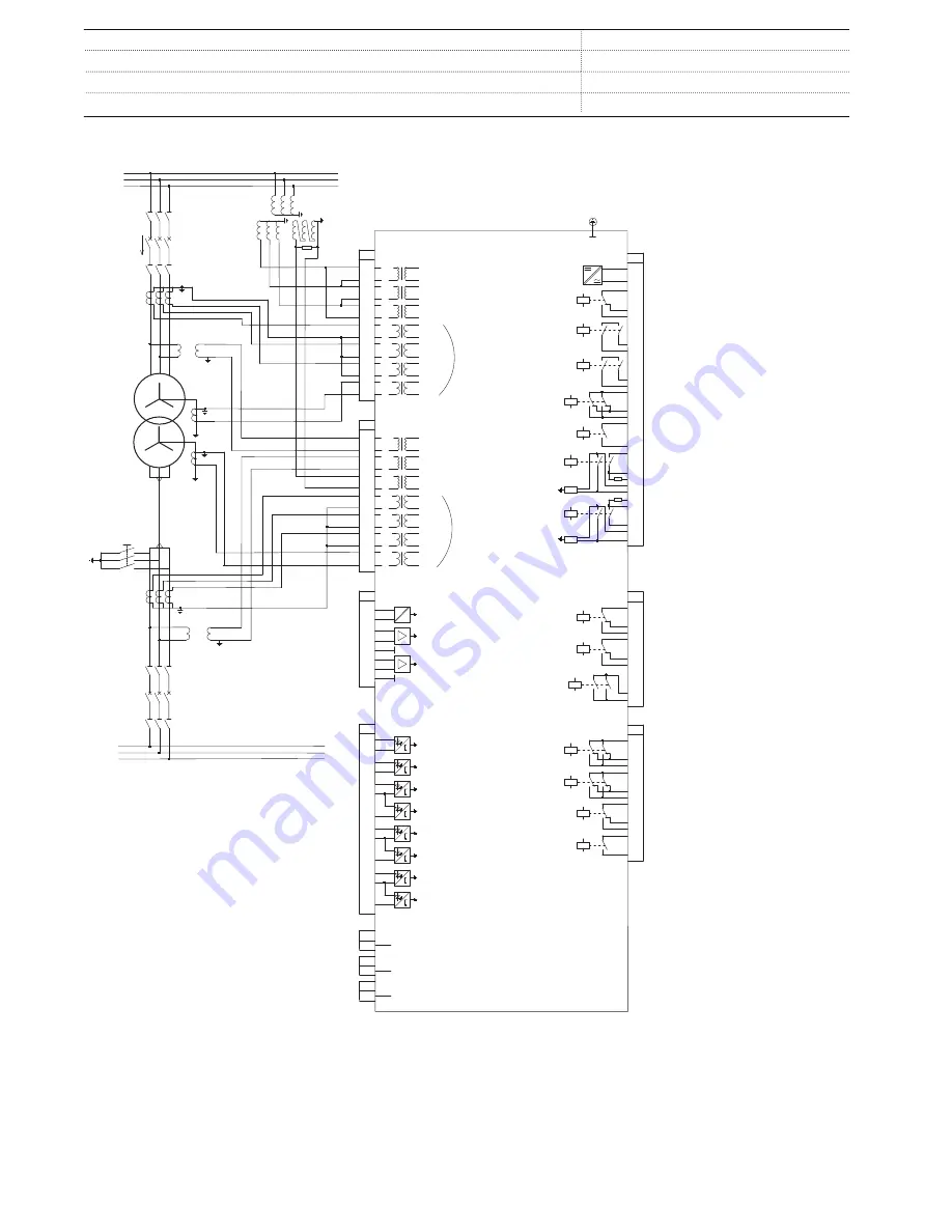
23. Connection diagrams
RET620
X13
Light sensor input 1 1)
X14
Light sensor input 2 1)
X15
Light sensor input 3 1)
16
17
19
18
X100
6
7
8
9
10
11
12
13
15
14
2
1
3
4
5
22
21
23
24
SO2
TCS2
PO4
SO1
TCS1
PO3
PO2
PO1
IRF
+
-
U
aux
20
X110
3
4
5
6
7
8
9
10
BI 6
BI 5
BI 4
BI 3
BI 2
BI 8
BI 7
12
13
11
BI 1
1
2
1) Order selectable -Optional
2) The IED features an automatic short-circuit
mechanism in the CT connector when plug-in
unit is detached
2)
X115
1
2
3
4
5
6
7
8
9
10
11
12
14
IoB
IL1B
IL2B
IL3B
1/5A
N
1/5A
N
1/5A
N
1/5A
N
13
Uo
60 -
N
210V
60 -
N
210V
60 -
N
210V
U_SYN
U_AVR
2)
X120
1
2
3
4
5
6
7
8
9
10
11
12
14
Io
IL1
IL2
IL3
1/5A
N
1/5A
N
1/5A
N
1/5A
N
13
U1
U2
U3
60 -
N
210V
60 -
N
210V
60 -
N
210V
X130
3
4
5
6
7
8
RTD 1
RTD 2
mA 1
mA
1
2
RTD 1 GND
RTD 2 GND
X130
10
9
11
13
12
14
16
17
SO2
SO1
SO3
L1
L2
L3
S1
S2
S2
S1
P1
P2
P1
P2
L1
L2
L3
LV
HV
a
n
N
A
da
dn
S1
S2
P1
P2
Uab
Uab
S1
S2
P1
P2
X110
16
14
15
19
17
18
22
20
21
SO3
23
SO4
24
SO1
SO2
Positive
Current
Direction
GUID-B8E8FE37-C9B8-45A0-953F-A3D0464FE251 V1 EN
Figure 14.
Connection for the A configuration
Transformer Protection and Control
1MRS757846 A
RET620
Product version: 2.0
54
ABB