


7.4.1.2
Completing the test
M13796-25 v5
Continue to test another function or end the testing by setting the parameter
TestMode to Off
under Main menu/Tests/IED test mode/TESTMODE:1. If another function is tested, then set
the parameter
Blocked to No under Main menu/Tests/Function test modes/Voltage/
UV2PTUV(27,2U<)/UV2PTUV:1 for the function, or for each individual function in a chain, to be
tested next. Remember to set the parameter
Blocked to Yes, for each individual function that
has been tested.
7.4.2
Two step overvoltage protection OV2PTOV
M13806-2 v6.1.1
Prepare the IED for verification of settings as outlined in the section
.
Values of the logical signals for OV2PTOV are available on the local HMI under Main menu/
Tests/Function status/Voltage/OV2PTOV(59,2U>)/OV2PTOV:1. The Signal Monitoring in
PCM600 shows the same signals that are available on the local HMI.
7.4.2.1
Verification of single-phase voltage and time delay to operate for Step 1
M13806-50 v5
1.
Apply single-phase voltage below the set value
U1>.
2.
Slowly increase the voltage until the ST1 signal appears.
3.
Note the operate value and compare it with the set value.
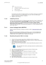
The operate value in secondary volts is calculated according to the
following equations:
For phase-to-ground measurement:
U
UBase VT
VTprim
1
100
3
>
×
×
sec
IECEQUATION2426 V1 EN-US
(Equation 16)
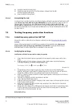
For phase-to-phase measurement:
U
UBase
VT
VTprim
1
100
>
×
×
sec
IECEQUATION2427 V1 EN-US
(Equation 17)
4.
Decrease the voltage slowly and note the reset value.
5.
Set and apply about 20% higher voltage than the measured operate value for one phase.
6.
Measure the time delay for the TR1 signal and compare it with the set value.
7.
Check the inverse time delay by injecting a voltage corresponding to 1.2 × U1>.
For example, if the inverse time curve A is selected, the trip signals TR1
and TRIP operate after a time corresponding to the equation:
t s
k
U
U
( )
=
>
−
1
1
1
IECEQUATION2429 V1 EN-US
(Equation 18)
where:
1MRK 505 293-UEN B
Section 7
Testing functionality
Breaker protection REQ650
67
Commissioning manual
© Copyright 2013 ABB. All rights reserved
Summary of Contents for REQ650 1.3 IEC
Page 1: ...Relion 650 SERIES Breaker protection REQ650 Version 1 3 IEC Commissioning manual ...
Page 2: ......
Page 12: ...6 ...
Page 20: ...14 ...
Page 28: ...22 ...
Page 40: ...34 ...
Page 42: ...36 ...
Page 116: ...110 ...
Page 123: ...117 ...


