


110
Two step definite and inverse time-
delayed residual
overcurrent protection (TEF1 and TEF2)
&KDSWHU
&XUUHQW
&DOFXODWLRQV
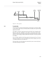
/RZFXUUHQWVWHS
The parameters for the two step definite and inverse time-delayed residual overcurrent
protection function are set via the local HMI or PST (Parameter Setting Tool). Refer to
the Technical reference manual for setting parameters and path in local HMI.
To detect high resistive earth-faults, a low operate current is required. On the other
hand, a low setting increases the risk for unwanted operation due to imbalance in the
network and the current transformer circuits. Set the minimum operate current
(IN>Low) of the earth-fault overcurrent protection higher than the maximum false
earth-fault current. If the directional function is chosen, set the start level of the direc-
tional function (IN> Dir) higher than the maximum false earth-fault current.
The choice of time delay characteristics - definite time, normal inverse, very inverse,
extremely inverse or RI inverse - depends on the network. To achieve optimum selec-
tivity, use the same type of characteristic for all earth-fault overcurrent protections in
the network. This means that in networks already equipped with earth-fault overcurrent
relays, the best selectivity is normally achieved by using the same type of characteristic
as in the existing relays.
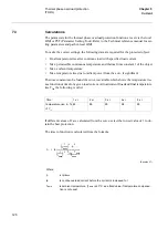
The following formulas for the operate time (in seconds) apply to the characteristic used
within the REO 517 terminal, see table 10.
7DEOH 2SHUDWHWLPHIRUPXODV
&KDUDFWHULVWLFV
2SHUDWHWLPHV
Normal inverse
(Equation 52)
Very inverse
(Equation 53)
Extremely inverse
(Equation 54)
RI inverse
(Equation 55)
t
0.14
I
0.02
1
–
--------------------
k
⋅
=
t
13.5
I
1
–
-----------
k
⋅
=
t
80
I
2
1
–
-------------
k
⋅
=
t
1
0 339
0 236
,
(
)
I
⁄
(
)
–
,
------------------------------------------------------
·
k
⋅
=
Summary of Contents for REO 517
Page 10: ... RQWHQWV ...
Page 16: ...6 Introduction to the application manual KDSWHU QWURGXFWLRQ ...
Page 64: ...54 Blocking of signals during test KDSWHU RPPRQ IXQFWLRQV ...
Page 88: ...78 Scheme communication logic ZCOM KDSWHU LQH LPSHGDQFH ...
Page 146: ...136 Unbalance protection for capacitor banks TOCC KDSWHU XUUHQW ...
Page 166: ...156 Dead line detection DLD KDSWHU 3RZHU V VWHP VXSHUYLVLRQ ...
Page 378: ...368 Monitoring of DC analog measurements KDSWHU 0RQLWRULQJ ...
Page 384: ...374 Pulse counter logic PC KDSWHU 0HWHULQJ ...
Page 412: ...402 Serial communication modules SCM KDSWHU DWD FRPPXQLFDWLRQ ...
Page 440: ...430 LED indication module KDSWHU DUGZDUH PRGXOHV ...