


107
Two step definite and inverse time-
delayed residual
overcurrent protection (TEF1 and TEF2)
&KDSWHU
&XUUHQW
/RZFXUUHQWVWHSIXQFWLRQ
Activate the independent time-delay function by setting
&KDUDFWHULVWLF
= Def (or inverse
time delay according to the setting table). The tLow timer starts when both the definite/
inverse time characteristic and the tMinInv timer operate. The tMinInv timer starts
when the I
N
current to the relay is equal to or higher than the set operate value for IN
>Low, the content of the second harmonic in I
N
is less than 20% and the directional con-
dition is fulfilled (if selected).
The inverse time calculation starts when I
N
is equal to or higher than the set operate val-
ue for IN>Low, the content of the second harmonic in I
N
is less than 20% and the di-
rectional condition is fulfilled (if selected). The inverse time delay is determined by the
selection of the characteristic (NI, VI etc.) in the Characteristic setting, the setting of the
characteristic IN>Inv current and the setting of the time multiplier k.
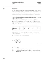
The tLow timer is normally set to zero. Use it to add a constant time to the inverse time
delay. Figure 48 shows the effect of the IN>Low and tMinInv settings on the inverse
characteristic.
)LJXUH 1RUPDOLQYHUVHDQGORJDULWKPLFLQYHUVHWLPHFKDUDFWHULVWLFV
+LJK&XUUHQWVWHSIXQFWLRQ
Activate the independent time delay function by setting
2SHUDWLRQ
=NonDir or Direc-
tional. The tHigh timer starts when the I
N
current to the relay is equal to or higher than
the set operate value for IN >High, the content of the second harmonic in I
N
is less than
20% and the directional condition is fulfilled (if selected).
1
2
3
4
5
1
2
3
5
7
10
20
30
50
Logaritmic
Inverse
Normal
Inverse
(k=0,4)
x IN>
t (s)
en02000546.vsd
tMinInv
IN>Low
Summary of Contents for REO 517
Page 10: ... RQWHQWV ...
Page 16: ...6 Introduction to the application manual KDSWHU QWURGXFWLRQ ...
Page 64: ...54 Blocking of signals during test KDSWHU RPPRQ IXQFWLRQV ...
Page 88: ...78 Scheme communication logic ZCOM KDSWHU LQH LPSHGDQFH ...
Page 146: ...136 Unbalance protection for capacitor banks TOCC KDSWHU XUUHQW ...
Page 166: ...156 Dead line detection DLD KDSWHU 3RZHU V VWHP VXSHUYLVLRQ ...
Page 378: ...368 Monitoring of DC analog measurements KDSWHU 0RQLWRULQJ ...
Page 384: ...374 Pulse counter logic PC KDSWHU 0HWHULQJ ...
Page 412: ...402 Serial communication modules SCM KDSWHU DWD FRPPXQLFDWLRQ ...
Page 440: ...430 LED indication module KDSWHU DUGZDUH PRGXOHV ...