When a hardware channel is connected, a graphical symbol appears in the Application
Configuration tool. The connection is also indicated in the Signal Matrix tool with a
cross mark. Hardware channels are always visible in the Signal Matrix tool.
Slot B (BIO).X1-1;4_BI1
Slot B (BIO).X1-2;4_BI2
Slot B (BIO).X1-3;4_BI3
Slot B (BIO).X1-5;8_BI4
Slot B (BIO).X1-6;8_BI5
Slot B (BIO).X1-7;8_BI6
T_R_TO_I8
REAL_IN
INT8_OUT
SlotC-RTD1
AI_VAL
HIGH_ALARM
HIGH_WARN
LOW_WARN
LOW_ALARM
SENSOR_FLT
TPOSYLTC1
BI0
BI1
BI2
BI3
BI4
BI5
END_POS_R
END_POS_L
SIGN_BIT
TAP_POS
TAP_POS
GUID-B8E3309E-44AA-4946-B730-D0BD4EF1DE9D V1 EN
Figure 47:
Application Configuration tool: HW signal channels
There are three types of supported hardware channels.
•
Binary input channels
•
Binary output channels
•
Analog input channels
A hardware input channel can be used as often as needed. A hardware binary output
channel is taken from the list of available channels when a new channel is requested.
This prevents using the same hardware binary output channel twice.
5.1.7.1
User-customized I/O channel configuration
Instead of pre-configured I/O channel connections to pre-processing function blocks,
user-customized configurations can be used. There are some rules which must be
followed to create a working configuration. Application Configuration automatically
checks if configuration is valid and results are shown in the output pane. See the
technical manual for the minimum I/O requirement per application function block.
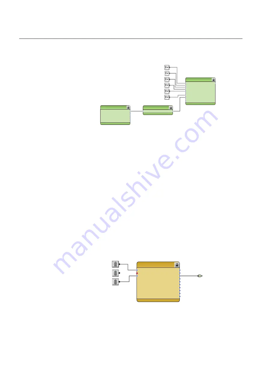
Example 1:
ILTCTR1
O:11|T:2,5|I:1
IL1
IL2
IL3
ALARM
WARNING
I3P
IRES_CLC
IRES_CLC_DR
IL1_DR
IL2_DR
IL3_DR
NPS_DR
PPS_DR
ILTCTR1[1]_I3P
Slot F (SIM).X1-Sensor_I
Slot F (SIM).X2-Sensor_I
Slot F (SIM).X3-Sensor_I
GUID-44490906-9B5A-4E36-AA18-94EF092C0465 V1 EN
Figure 48:
Missing required input connection for output
Section 5
1MRS759117 A
Protection and control engineering
72
REX640
Engineering Manual


