


Terminology
The busbar voltage UB is a shorter notation for the measured voltages Ua, Ub, Uc
or Uij, where Uij is the phase-phase voltage, Uij = Ui -Uj, or Ui, where Ui is one
single-phase-to-earth voltage.
I
L
is a shorter notation for the measured load current; it is to be used instead of the
three-phase quantities Ia, Ib, Ic or the two-phase quantities Ii and Ij, or single-phase
current Ii.
Also note that for simplicity, the Parameter Setting menu structures
included in the following procedure are referred to universally as
VCP1, for example,
Main menu/Settings/Setting Group N/
Control/TransformerVoltageControl(ATCC,90)/VCSx/VCPx/
Time/t1 and t2l
.
For cases where single-mode voltage control is implemented, the Parameter Setting
menu structure includes VCS1 instead of the parallel designator VCP1.
13.11.4.1
Secondary test
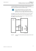
The voltage control function performs basic voltage regulation by comparing a
calculated load voltage (U
L
) against a voltage range defined by setting
UDeadband
(with upper and lower limits U2 and U1 respectively). The calculated load voltage
U
L
represents the secondary transformer bus voltage UB adjusted for Load drop
compensation (LDC) where enabled in settings.
Note that when LDC is disabled, UB equals U
L
.
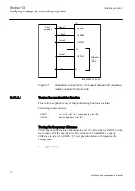
When the load voltage U
L
stays within the interval between U1 and U2, no action
will be taken.
If U
L
< U1 or U
L
> U2, a command timer will start, which is constant time or
inverse time defined by setting
t1
and
t1Use
. The command timer will operate
while the measured voltage stays outside the inner deadband (defined by setting
UDeadbandInner
).
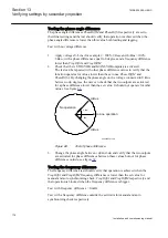
If U
L
remains outside of the voltage range defined by
UDeadband
and the
command timer expires, the voltage control will execute a raise or lower command
to the transformer tap changer. This command sequence will be repeated until U
L
is brought back within the inner deadband range.
13.11.4.2
Check the activation of the voltage control operation
Section 13
1MRK 504 088-UEN C
Verifying settings by secondary injection
184
Installation and commissioning manual
Summary of Contents for RELION RET670
Page 1: ...Relion 670 series Transformer protection RET670 Installation and commissioning manual...
Page 2: ......
Page 16: ...10...
Page 24: ...18...
Page 26: ...20...
Page 28: ...22...
Page 82: ...76...
Page 88: ...82...
Page 94: ...88...
Page 104: ...98...
Page 110: ...104...
Page 210: ...204...
Page 230: ...224...
Page 239: ...233...


