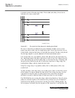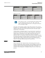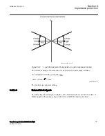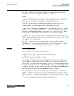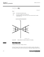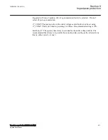
Phase-to-phase loop
Voltage phasor
Current phasor
A-B
VAB
IAB
B-C
VBC
IBC
C-A
VCA
ICA
Enhanced reach loop
Max current
Loop selected
Voltage phasor
Current phasor
IA
A-G
VAG-V0
IA
IB
B-G
VBG-V0
IB
IC
C-G
VCG-V0
IC
If the currents are equal, A–G loop has higher priority than B-G and B-
G loop has higher priority than C-G. VAG, VBG, VCG are three
phase–to–ground voltages and IA, IB, IC are three phase currents and
V0 is zero sequence voltage.
To measure correct impedance for phase-to-phase faults on HV side of the generator
transformer, it is recommended that
EnhancedReach
option (phase-to-ground loop with
maximum current loop) is used. For three-phase faults on HV side, phase-to-phase
loop measures correct impedance.
In
EnhancedReach
, compensation signal V0 is used to prevent zone 2 operating for
ground faults in the generator. In the absence of this compensation, when a ground
fault takes place in the generator side, the voltage drops and the load current in the
machine leads due to which zone 2 element picks up resulting in misleading
indications. Zone 2 is not intended to operate for the generator winding ground faults.
The protection for generator winding ground fault is provided by sensitive ground fault
relays that are time delayed. To prevent such an operation, the phase-to-ground
measuring voltage is compensated with zero sequence voltage V0. This prevents the
function from operating during the generator stator ground faults.
8.21.2.4
Zone 3 operation
GUID-131391BB-2E2A-4EEB-B021-D996AEC84524 v4
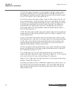
Zone 3 covers the HV side of the transformer, interconnecting station bus to the
network and outgoing lines. Within its operating zone, the tripping time for this relay
should be coordinated with the longest time delay of the phase distance relays on the
transmission lines connected to the generating substation bus. It is normally set to
about 80% of the load impedance considering maximum short time overload on the
generator.
1MRK 504 163-UUS A
Section 8
Impedance protection
Transformer protection RET670 2.2 ANSI
505
Application manual
Summary of Contents for RELION RET670
Page 1: ...RELION 670 SERIES Transformer protection RET670 Version 2 2 ANSI Application manual ...
Page 2: ......
Page 48: ...42 ...
Page 64: ...58 ...
Page 74: ...68 ...
Page 104: ...98 ...
Page 194: ...188 ...
Page 518: ...512 ...
Page 618: ...612 ...
Page 648: ...642 ...
Page 666: ...660 ...
Page 672: ...666 ...
Page 682: ...676 ...
Page 844: ...838 ...
Page 868: ...862 ...
Page 956: ...950 ...
Page 964: ...958 ...
Page 1004: ...998 ...
Page 1014: ...1008 ...
Page 1015: ...1009 ...

