
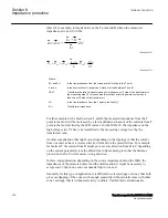


The default setting of
IMinPUPP
and
IMinPUPG
is 20% of
IBase
where
IBase
is the
chosen current for the analogue input channels. The value has been proven in practice
to be suitable in most of the applications. However, there might be applications where
it is necessary to increase the sensitivity by reducing the minimum operating current
down to 10% of
IBase
. This happens especially in cases, when the IED serves as a
remote back-up protection on series of very long transmission lines.
Setting
IMinOpIR
blocks the phase-to-ground loop if 3I
0
<
IMinOpIR
. The default
setting of
IMinOpIR
is 5% of
IBase
.
The minimum operating fault current is automatically reduced to 75% of its set value,
if the distance protection zone has been set for the operation in reverse direction.
8.9.3.10
Setting of timers for distance protection zones
GUID-E6DD460D-2189-45E9-AD4D-E127DCA8EBAC v1
The required time delays for different distance protection zones are independent of
each other. Distance protection zone 1 can also have a time delay, if so required for
selectivity reasons. Time delays for all zones can be set in a range of 0 to 60 seconds.
The tripping function of each particular zone can be inhibited by setting the
corresponding
Operation
parameter to
Off
. Different time delays are possible for the
phase-to-ground
tPG
and for the phase-to-phase
tPP
measuring loops in each distance
protection zone separately, to further increase the total flexibility of a distance
protection.
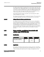
8.10
Phase selection, quadrilateral characteristic with
settable angle FRPSPDIS (21)
GUID-29E9C424-5AF7-40EE-89D9-F6BB4F0A0836 v2
8.10.1
Identification
GUID-07DB9506-656C-4E5F-A043-3DAA624313C7 v2
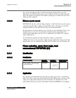
Function description
IEC 61850
identification
IEC 60617
identification
ANSI/IEEE C37.2
device number
Phase selection, quadrilateral
characteristic with settable angle
FRPSPDIS
Z<phs
SYMBOL-DD V1 EN-US
21
8.10.2
Application
GUID-D07A7B62-FDB9-4728-859A-9CE7423BE128 v1
The operation of transmission networks today is in many cases close to the stability
limit. The ability to accurately and reliably classify the different types of fault, so that
single pole tripping and autoreclosing can be used plays an important role in this
1MRK 504 163-UUS A
Section 8
Impedance protection
Transformer protection RET670 2.2 ANSI
345
Application manual
Summary of Contents for RELION RET670
Page 1: ...RELION 670 SERIES Transformer protection RET670 Version 2 2 ANSI Application manual ...
Page 2: ......
Page 48: ...42 ...
Page 64: ...58 ...
Page 74: ...68 ...
Page 104: ...98 ...
Page 194: ...188 ...
Page 518: ...512 ...
Page 618: ...612 ...
Page 648: ...642 ...
Page 666: ...660 ...
Page 672: ...666 ...
Page 682: ...676 ...
Page 844: ...838 ...
Page 868: ...862 ...
Page 956: ...950 ...
Page 964: ...958 ...
Page 1004: ...998 ...
Page 1014: ...1008 ...
Page 1015: ...1009 ...


