—
RELION® PROTECTION AND CONTROL
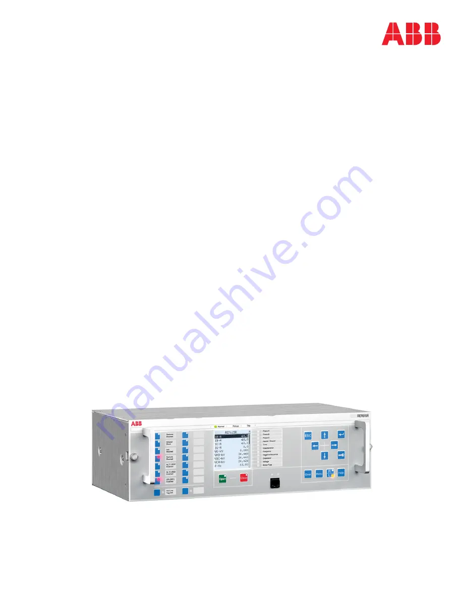
REF615R
Installation Manual
Page 1: ... RELION PROTECTION AND CONTROL REF615R Installation Manual ...
Page 2: ......
Page 3: ...Document ID 1MRS240046 IB Issued 2019 07 02 Revision B Product version 4 1 Copyright 2019 ABB All rights reserved ...
Page 4: ...t is furnished under a license and may be used copied or disclosed only in accordance with the terms of such license Trademarks ABB and Relion are registered trademarks of the ABB Group All other brand or product names mentioned in this document may be trademarks or registered trademarks of their respective holders Warranty Please inquire about the terms of warranty from your nearest ABB represent...
Page 5: ...cted and communicate data and information via a network interface which should be connected to a secure network It is the sole responsibility of the person or entity responsible for network administration to ensure a secure connection to the network and to take the necessary measures such as but not limited to installation of firewalls application of authentication measures encryption of data inst...
Page 6: ...e within specified voltage limits Low voltage directive 2006 95 EC This conformity is the result of tests conducted by ABB in accordance with the product standards EN 50263 and EN 60255 26 for the EMC directive and with the product standards EN 60255 1 and EN 60255 27 for the low voltage directive The product is designed in accordance with the international standards of the IEC 60255 series and AN...
Page 7: ...always be followed The frame of the protection relay has to be carefully grounded When the plug in unit has been detached from the case do not touch the inside of the case The relay case internals may contain high voltage potential and touching these may cause personal injury The protection relay contains components which are sensitive to electrostatic discharge Unnecessary touching of electronic ...
Page 8: ......
Page 9: ... 9 Inspecting product and delivery items 9 Identifying product 9 Checking delivery items 9 Inspecting product 9 Returning a product damaged in transit 10 Storing 10 Section 4 Mounting 11 Checking environmental conditions and mounting space 11 Detaching and installing the plug in unit 11 Detaching the plug in unit 11 Installing the plug in unit 13 Mounting the IED 14 Required tools 14 Rack mounting...
Page 10: ...ssembly of the IED 27 Section 6 Removing repairing and exchanging 29 Product lifecycle 29 Checking protection relay information 29 Removing the IED 30 Sending protection relay for repair 30 Exchanging protection relay 30 Section 7 Technical data 31 Case and HMI display variants 31 Front side of the IED 31 Rear side of the IED 32 Dimensions 33 Enclosure class 34 Section 8 Accessories and ordering d...
Page 11: ...lectrical installation The chapters are organized in the chronological order in which the relay should be installed 1 2 Intended audience This manual addresses the personnel responsible for installing the product hardware The installation personnel must have basic knowledge of handling electronic equipment 1MRS240046 IB B Section 1 Introduction REF615R 3 Installation Manual ...
Page 12: ... list manual GUID 3983CF6E DF22 4183 B387 D67F3BB9593C V1 EN Figure 1 The intended use of documents during the product life cycle 1 3 2 Document revision history Document revision date Product version History A 2013 11 22 4 0 First release B 2019 07 02 4 1 Content updated Download the latest documents from the ABB Web site http www abb com substationautomation 1 3 3 Related documentation Product s...
Page 13: ...o design your project or how to use a certain function Although warning hazards are related to personal injury it is necessary to understand that under certain operational conditions operation of damaged equipment may result in degraded process performance leading to personal injury or death Therefore comply fully with all warning and caution notices 1 4 2 Document conventions A particular convent...
Page 14: ...e enabled and disabled with the Operation setting Parameter values are indicated with quotation marks The corresponding parameter values are Enabled and Disabled Input output messages and monitored data names are shown in Courier font When the function picks up the PICKUP output is set to TRUE Dimensions are provided both in inches and mm If it is not specifically mentioned the dimension is in mm ...
Page 15: ... diphenyl ethers PBDE 0 1 Operational reliability and long life time have been assured with extensive testing during the design and manufacturing processes Moreover long life time is supported by maintenance and repair services as well as by the availability of spare parts Design and manufacturing have been done under a certified environmental system The effectiveness of the environmental system i...
Page 16: ... 2 Materials of the protection relay parts Protection relay Parts Material Case Metallic plates parts and screws Steel aluminium Plastic parts PC1 LCP2 Electronics plug in module Various Plug in unit Electronics plug in modules Various Electronics LHMI module Various Plastic parts PC PBT3 LCP PA4 Metallic parts Aluminium Package Box Cardboard Attached material Manuals Paper 1 Polycarbonate 2 Liqui...
Page 17: ... Locate the protection relay s order number from the label on top of the plug in unit 2 Compare the protection relay s order number with the ordering information to verify that the received product is correct 3 2 2 Checking delivery items Check that all items are included in the delivery in accordance with the delivery documents 3 2 3 Inspecting product Protection relays require careful handling b...
Page 18: ...arrier Please inform the nearest ABB office or representative Notify ABB immediately if there are any discrepancies in relation to the delivery documents 3 3 Storing If the protection relay is stored before installation it must be done in the original transport casing in a dry and dust free place in accordance with ANSI C37 90 0 Observe the environmental requirements stated in the technical manual...
Page 19: ...at sufficient space is available Sufficient space is needed at the front and rear of the IED to allow access to wires and optical fibers and to enable maintenance and future modifications For more details of the checks required for different type of mounting methods see the respective chapters such as rack mounting or flush mounting 4 2 Detaching and installing the plug in unit 4 2 1 Detaching the...
Page 20: ... side of the front panel and pulling the unit straight forward Pulling the board out at an angle or otherwise stressing the board on extraction may damage the unit Once removed from the case position the unit face down on a static secured mat Do not touch terminals inside the case after removing the plug in unit Live terminals can be inside the case The signal connectors are left open when the plu...
Page 21: ... 2 Tray guide bracket 2 Push the unit straight inward until it fully seats in the case 3 Secure the knurled screws 4 Push in the sealing wires and secure if necessary Make sure that the unit plugged in corresponds to the case in which it is inserted based on application requirements Check that the plug in unit and the case have the same serial number or compatible order code numbers before fitting...
Page 22: ...Use only adjustable torque screwdrivers 5 16 wrench 1 16 wrench or hex nut driver 4 3 2 Rack mounting the IED REF615R is supplied with mounting brackets attached for direct mounting on 19 inch rack system The IED occupies 3U height in the rack system No additional components are required Section 4 1MRS240046 IB B Mounting 14 REF615R Installation Manual ...
Page 23: ...25 mm and additional depth for the wires fiber optic cables can easily swing out from the panel Provide at least 2U space above and below the unit to provide adequate ventilation for the IED as well as for the other units in the neighbourhood Check that either the rack is in a dust proof panel or the room in which the rack is mounted is well insulated from environmental dust water ingress and so o...
Page 24: ...ID E9598552 2B0B 4936 9C93 F4F668120119 V1 EN Figure 5 Moving the rack mounting brackets Check the allowed minimum bending radius from the optical cable manufacturer 4 3 3 Flush mounting or semi flush mounting the IED A mounting kit is needed when flush mounting or semi flush mounting the IED in a panel Section 4 1MRS240046 IB B Mounting 16 REF615R Installation Manual ...
Page 25: ...6 Bezel gasket ABB 613641 1 Requirements for installation Panel cut out and holes for mounting screws as shown in Figure 7 For flush mounting depth behind the panel should be about 9 inches 228 6 mm Add about 2 inches space for wire cable duct and so on It should be possible to add or replace the flush mounted IED without excessive dismantling When space at the rear is a constrain check if semi fl...
Page 26: ...4 0 mm B 18 500 in 469 9 mm F 5 562 in 141 3 mm C 6 0 220 in 5 6 mm G 5 630 in 143 0 mm D 17 500 in 444 5 mm H 4 R 030 0 76 max 1 If the IED is with rack mounting brackets on either side loosen the four 6 32 fixing screws and remove the brackets Store them away as spares or for future use 2 Remove the set screws from the top of the case 3 Slip the bezel frame over the IED case with flange towards ...
Page 27: ...se on the panel by inserting the bezel through the panel cut out 6 Attach the unit to the panel by inserting bezel studs through the panel s drilled holes Use 10 32 hex nuts with lock washer from the bezel kit to secure the bezel 7 Position the clear plastic dust cover if ordered on the front of the IED and tighten thumb screws to the bezel studs The cover can be used only for flush mounted instal...
Page 28: ...rc flash detector system Arc flash detector is used to detect arc situations in air insulated metal clad switchgear The arc flash detector system determines where in the switchgear cubicle the optional lens sensors are installed See the application examples in the application manual for further information on the alternatives Section 4 1MRS240046 IB B Mounting 20 REF615R Installation Manual ...
Page 29: ...37 inches 9 5 mm D 0 75 inches 19 1 mm 2 Fit the lens sensor into the hole and fasten it with a self tapping M3 screw Alternatively the lens sensor can be fastened with a cable tie To do this secure the cable tie to a suitable point of attachment on the cubicle wall and wrap the cable tie tightly around the sensor 1MRS240046 IB B Section 4 Mounting REF615R 21 Installation Manual ...
Page 30: ... V1 EN Figure 11 Mounting the lens sensor 3 Make sure that the cable tie lies in the groove of the sensor to prevent it from blocking the light Section 4 1MRS240046 IB B Mounting 22 REF615R Installation Manual ...
Page 31: ... 14 or 16 Gauge wire Use 12 or 14 Gauge wire for CB trip circuit Connect each ring lug terminal for CTs VTs with one 12 Gauge wire See the application manual for product specific connection diagrams 5 3 Connecting protective grounding The ground lead must be at least a 10 Gauge wire If the ground lead is long the cross section of the wire must be increased Use fine copper wire as the ground lead 1...
Page 32: ...2D0E5FA34 V1 EN Figure 12 The protective ground screw is located at the rear of the IED The ground lead should be as short as possible but extra length is required for door mounting Each IED must have its own ground lead connected to the ground circuit connector 2 Connect the ground lead to the ground bar Use either stripped wire screwed between a washer cup and the protective ground screw or a ri...
Page 33: ...the wires for the binary signals to the correct device according to the connection diagram Each terminal for binary input and output signal is dimensioned for one 14 or 16 Gauge wire 5 7 Connecting power supply Always make sure the IED s ground terminal is connected and grounded effectively Connect the auxiliary voltage of the IED to terminals 1 and 2 Connect the positive lead to terminal 1 The pe...
Page 34: ... GUID C95C7D11 B41B 4559 ADDF 841BC7D00678 V1 EN Figure 13 Connecting auxiliary voltage 5 8 Connecting communication Before connecting communication check that the HW module has the correct communication interfaces The communication module is located on the left side of the IED when viewing the case from the rear See the technical manual for product specific communication interfaces 5 9 Energizing...
Page 35: ...oards at site For any repairs of boards or assemblies please contact your local ABB representative 1 6 2 5 7 8 4 3 GUID 71F99083 9085 436F 916D 26DC7DB9CF5B V1 EN Figure 14 Inner boards and components assembly of REF615R 1 Backplane PCB 5 CCEB 2 PSM card 6 BIO card 3 AIM3016 3017 card 7 Adaptor PCB 4 COM card 8 AIM3006 card 1MRS240046 IB B Section 5 Connecting REF615R 27 Installation Manual ...
Page 36: ...28 ...
Page 37: ... number The protection relay information is shown on the display for a few seconds when the device starts up The same information is found also in the protection relay menu 1 Select Main Menu Information 2 Select a submenu with and 3 Enter the selected submenu with 4 Browse the information with and The Product identifiers submenu contains product related information like product type serial number...
Page 38: ... for consultation and instructions 6 5 Exchanging protection relay To exchange the protection relay with another identical unit remove the protection relay and install the new one The exchangeable units can be found from the PartsOnLine system see www abb com partsonline Use of PartsOnLine requires user registration To exchange a protection relay to a different unit change the case and connect the...
Page 39: ...5FAE 18FD 4343 8069 20D4182E81E4 V1 EN Figure 15 Front view with LHMI ANSI variant GUID 497C4732 55E5 483A 89AE F8BACFE8DF36 V1 EN Figure 16 Front view with LHMI IEC variant Table 3 Large display Character size Rows in the view Characters per row Small mono spaced 6 12 pixels 10 20 1MRS240046 IB B Section 7 Technical data REF615R 31 Installation Manual ...
Page 40: ...D OUTPUT OPTION HIGH SPEED OUTPUT WITH HIGH SPEED OUTPUT OPTION SINGLE ENDED INPUT WITH HIGH SPEED OUTPUT OPTION FOR HWFAxxxx33xxxxxxxx REFER TO TECHNICAL MANUAL FOR X5 PIN ASSIGNMENTS OUT5 OUT4 COM OUT6 X5 PIN DPU PIN CONNECTIONS IRIG B 5 63 IRIG B 6 57 RS 485 comm 7 56 RS 485 8 55 RS 485 9 59 Direction 10 58 Direction 15 14 13 12 11 10 9 8 7 6 5 4 3 2 1 18 19 20 21 22 23 24 25 26 27 28 29 30 4 6...
Page 41: ...5 mm K 9 08 in 230 6 mm E 6 58 in 167 1 mm L 8 33 in 211 6 mm F 1 00 in 25 4 mm M 1 59 in 40 4 mm G 19 00 in 482 6 mm Table 4 Dimensions Description Value Width With mounting ears 19 in 482 6 mm Without mounting ears 17 12 in 434 8 mm Height 5 22 in 132 6 mm Depth 9 08 in 230 7 mm Weight Complete protection relay 11 9 lb 5 4 kg Plug in unit inner chassis only 5 1 lb 2 31 kg 1MRS240046 IB B Section...
Page 42: ...losure class Table 5 Degree of protection of flush mounted protection relay Description Value Front side with dust cover accessory IP 54 Section 7 1MRS240046 IB B Technical data 34 REF615R Installation Manual ...
Page 43: ... for optical sensors for arc protections 5 0 m 1MRS120534 5 0 Table 8 Mounting accessories Item Order number Bezel cover kit for panel mounting 2RGA018542A0001 Table 9 Spare parts Item Order number RJ45 plug 2RGA019358P0001 Table 10 Test switches Item Order number FT 1 FT 14 and FT 19 Flexitest switches See Descriptive bulletins DB 41 077 and DB 41 078 on www abb com substationautomation 1MRS24004...
Page 44: ...36 ...
Page 45: ...ernet protocol LCD Liquid crystal display LCP Liquid crystal polymer LED Light emitting diode LHMI Local human machine interface PA Polyamide PBT Polybutylene terephthalate PC 1 Personal computer 2 Polycarbonate PCB Printed circuit board PSM Power supply module RoHS Restriction of hazardous substances SW Software UL Underwriters Laboratories VT Voltage transformer WHMI Web human machine interface ...
Page 46: ...38 ...
Page 47: ...39 ...
Page 48: ...O Box 699 FI 65101 VAASA Finland Phone 358 10 22 11 ABB Inc 655 Century Point Lake Mary FL 32746 USA Phone 1 800 222 1946 www abb com mediumvoltage www abb com relion www abb com substationautomation Copyright 2019 ABB All rights reserved 1MRS240046 IB B ...