


15.4.2
Principle of operation
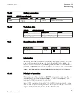
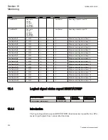
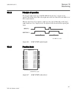
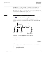
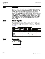
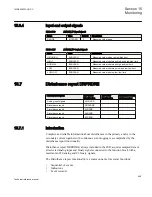
The Logical signal status report (BINSTATREP) function has 16 inputs and 16
outputs. The output status follows the inputs and can be read from the local HMI or via
SPA communication.
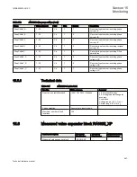
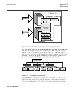
When an input is set, the respective output is set for a user defined time. If the input
signal remains set for a longer period, the output will remain set until the input signal
resets.
t
t
INPUTn
OUTPUTn
IEC09000732-1-en.vsd
IEC09000732 V1 EN
Figure 466:
BINSTATREP logical diagram
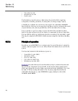
15.4.3
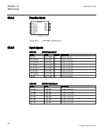
Function block
BINSTATREP
BLOCK
^INPUT1
^INPUT2
^INPUT3
^INPUT4
^INPUT5
^INPUT6
^INPUT7
^INPUT8
^INPUT9
^INPUT10
^INPUT11
^INPUT12
^INPUT13
^INPUT14
^INPUT15
^INPUT16
OUTPUT1
OUTPUT2
OUTPUT3
OUTPUT4
OUTPUT5
OUTPUT6
OUTPUT7
OUTPUT8
OUTPUT9
OUTPUT10
OUTPUT11
OUTPUT12
OUTPUT13
OUTPUT14
OUTPUT15
OUTPUT16
IEC09000730-1-en.vsd
IEC09000730 V1 EN
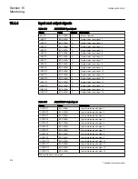
Figure 467:
BINSTATREP function block
1MRK505222-UUS C
Section 15
Monitoring
937
Technical reference manual
Summary of Contents for Relion 670 series
Page 1: ...Relion 670 series Line differential protection RED670 ANSI Technical reference manual...
Page 2: ......
Page 40: ...34...
Page 50: ...44...
Page 60: ...54...
Page 126: ...120...
Page 384: ...378...
Page 496: ...490...
Page 556: ...550...
Page 602: ...596...
Page 620: ...614...
Page 794: ...788...
Page 864: ...858...
Page 988: ...982...
Page 998: ...992...
Page 1084: ...1078...
Page 1164: ...1158...
Page 1168: ...1162...
Page 1220: ...1214...
Page 1230: ...1224...
Page 1231: ...1225...