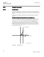
-3V
0
=V
ref
RCA = 0
°
Operate area
Instrument
transformer
angle error
3I
0
(prim)
3I
0
(to prot)
a
Characteristic after
angle compensation
RCAcomp
en06000651_ansi.vsd
ANSI06000651 V1 EN
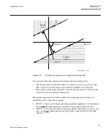
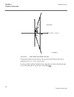
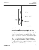
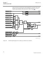
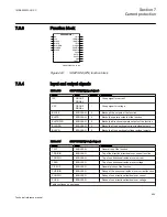
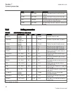
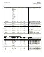
Figure 221:
Explanation of RCAComp
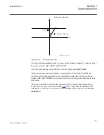
Directional residual power protection measuring 3I
0
· 3V
0
· cos φ
φ is defined as the angle between the residual current 3I
0
and the reference voltage
compensated with the set characteristic angle
RCADir
(φ=ang(3I
0
)—ang(V
ref
) ). V
ref
=
-3V
0
e
-jRCA
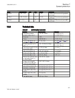
. The function operates when 3I
0
· 3V
0
· cos φ gets larger than the set value.
For trip, both the residual power 3I
0
· 3V
0
· cos φ, the residual current 3I
0
and the
release voltage 3V
0
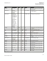
, shall be larger than the set levels (
SN_PU
,
INRelPU
and
VNRelPU
).
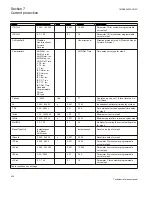
Trip from this function can be blocked from the binary input BLKTRDIR.
When the function is activated binary output signals PICKUP and PUDIRIN are
activated. If the output signals are active after the set delay
tDef
or after the inverse
time delay (setting
TDSN
) the binary output signals TRIP and TRDIRIN are activated.
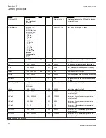
The function shall indicate forward/reverse direction to the fault. Reverse direction is
defined as 3I
0
· 3V
0
·cos (φ + 180°)
³
the set value.
1MRK505222-UUS C
Section 7
Current protection
441
Technical reference manual
Summary of Contents for Relion 670 series
Page 1: ...Relion 670 series Line differential protection RED670 ANSI Technical reference manual...
Page 2: ......
Page 40: ...34...
Page 50: ...44...
Page 60: ...54...
Page 126: ...120...
Page 384: ...378...
Page 496: ...490...
Page 556: ...550...
Page 602: ...596...
Page 620: ...614...
Page 794: ...788...
Page 864: ...858...
Page 988: ...982...
Page 998: ...992...
Page 1084: ...1078...
Page 1164: ...1158...
Page 1168: ...1162...
Page 1220: ...1214...
Page 1230: ...1224...
Page 1231: ...1225...

