background image

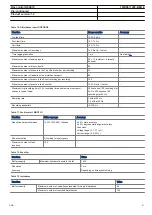
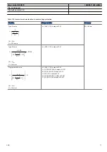
Table 102. Inverse time characteristics for undervoltage protection

Function

Range or value

Accuracy

Type A curve:

=

< -

<

æ

ö

ç

÷

è

ø

k

t

U

U

U

EQUATION1431-SMALL V1 EN

U< = U

set

U = UV

measured

k = (0.05-1.10) in steps of 0.01

5% +40 ms

Type B curve:

2.0

480

0.055

32

0.5

×

=

+

< -

×

-

<

æ

ö

ç

÷

è

ø

k

t

U

U

U

EQUATION1432-SMALL V1 EN

U< = U

set

U = U

measured

k = (0.05-1.10) in steps of 0.01

Programmable curve:

×

=

+

< -

×

-

<

é

ù

ê

ú

ê

ú

ê

ú

æ

ö

ê

ú

ç

÷

ëè

ø û

P

k A

t

D

U

U

B

C

U

EQUATION1433-SMALL V1 EN

U< = U

set

U = U

measured

k = (0.05-1.10) in steps of 0.01
A = (0.005-200.000) in steps of 0.001
B = (0.50-100.00) in steps of 0.01
C = (0.0-1.0) in steps of 0.1
D = (0.000-60.000) in steps of 0.001
P = (0.000-3.000) in steps of 0.001

Bay control REC670

1MRK511232-BEN E

Pre-configured


Product version: 1.2


ABB

73

Summary of Contents for Relion 670 series REC670

Page 1: ...Relion 670 series Bay control REC670 Pre configured Product Guide ...

Page 2: ... Hardware description 20 19 Connection diagrams 22 20 Technical data 29 21 Ordering 75 Disclaimer The information in this document is subject to change without notice and should not be construed as a commitment by ABB ABB assumes no responsibility for any errors that may appear in this document Copyright 2012 ABB All rights reserved Trademarks ABB and Relion are registered trademarks of the ABB Gr...

Page 3: ...nd overvoltage functions are examples of the available functions allowing user to fulfill any application requirement REC670 has been provided with six of overcurrent earth fault autorecloser and measuring functions This together with the multi display local HMI allows use as multi feeder protection and controller for distribution buses Disturbance recording and fault locator are available to allo...

Page 4: ...ncluded in packages A03 refer to ordering details IEC 61850 ANSI Function description Bay control REC670 A30 REC670 B30 REC670 C30 Differential protection HZPDIF 87 1Ph high impedance differential protection 3 A02 3 A02 6 A07 Bay control REC670 1MRK511232 BEN E Pre configured Product version 1 2 4 ABB ...

Page 5: ...t 1 C31 1 C32 2 C33 CCRBRF 50BF Breaker failure protection 1 C31 2 C32 3 C33 CCRPLD 52PD Pole discordance protection 1 2 3 GUPPDUP 37 Directional underpower protection 1 C17 1 C17 1 C17 GOPPDOP 32 Directional overpower protection 1 C17 1 C17 1 C17 BRCPTOC 46 Broken conductor check 1 1 1 Voltage protection UV2PTUV 27 Two step undervoltage protection 2 D02 2 D02 2 D02 OV2PTOV 59 Two step overvoltage...

Page 6: ...l 1 H15 1 H15 2 H18 TCMYLTC 84 Tap changer control and supervision 6 binary inputs 4 4 4 TCLYLTC 84 Tap changer control and supervision 32 binary inputs 4 4 4 SLGGIO Logic rotating switch for function selection and LHMI presentation 15 15 15 VSGGIO Selector mini switch 20 20 20 DPGGIO IEC61850 generic communication I O functions 16 16 16 SPC8GGIO Single pole generic control 8 signals 5 5 5 Automat...

Page 7: ...itoring CVMMXN Measurements 6 6 6 EVENT Event function 20 20 20 DRPRDRE Disturbance report 1 1 1 SPGGIO IEC61850 generic communication I O functions 64 64 64 SP16GGIO IEC61850 generic communication I O functions 16 inputs 16 16 16 MVGGIO IEC61850 generic communication I O functions 24 24 24 BSStatReport Logical signal status report 3 3 3 RANGE_XP Measured value expander block 66 66 66 LMBRFLO Faul...

Page 8: ...ceive 10 10 10 Multiple command and transmit 60 10 60 10 60 10 Ethernet configuration of links 1 1 1 IEC 62439 3 Edition 1 parallel redundancy protocol 1 P01 1 P01 1 P01 IEC 62439 3 Edition 2 parallel redundancy protocol 1 P02 1 P02 1 P02 Scheme communication ZCPSCH 85 Scheme communication logic for distance or overcurrent protection 1 K01 1 K01 1 K01 ZCRWPSCH 85 Current reversal and weak end infe...

Page 9: ...ication mapping 1 DOSFRNT Denial of service frame rate control for front port 1 DOSOEMAB Denial of service frame rate control for OEM port AB 1 DOSOEMCD Denial of service frame rate control for OEM port CD 1 3 Differential protection 1Ph High impedance differential protection HZPDIF The 1Ph High impedance differential protection HZPDIF function can be used when the involved CT cores have the same ...

Page 10: ...well EF4PTOC can be configured to measure the residual current from the three phase current inputs or the current from a separate current input Four step negative sequence overcurrent protection NS4PTOC Four step negative sequence overcurrent protection NS4PTOC has an inverse or definite time delay independent for each step separately All IEC and ANSI time delayed characteristics are available tog...

Page 11: ...g machines and can cause unwanted operation of zero sequence or negative sequence current functions Normally the own breaker is tripped to correct such a situation If the situation persists the surrounding breakers should be tripped to clear the unsymmetrical load situation The Polediscordance protection function CCRPLD operates based on information from auxiliary contacts of the circuit breaker f...

Page 12: ...d restoring SAPTOF is provided with an undervoltage blocking The operation is based on positive sequence voltage measurement and requires two phase phase or three phase neutral voltages to be connected For information about how to connect analog inputs refer to Application manual IED application Analog inputs Setting guidelines Rate of change frequency protection SAPFRC Rate of change frequency pr...

Page 13: ... SESRSYN function checks that the voltages on both sides of the circuit breaker are in synchronism or with at least one side dead to ensure that closing can be done safely SESRSYN function includes a built in voltage selection scheme for double bus and 1 breaker or ring busbar arrangements Manual closing as well as automatic reclosing can be checked by the function and can have different settings ...

Page 14: ...require exchange of information between the parallel transformers and this is provided for within IEC61850 8 1 Voltage control includes many extra features such as possibility of to avoid simultaneous tapping of parallel transformers hot stand by regulation of a transformer in a group which regulates it to a correct tap position even though the LV CB is open compensation for a possible capacitor b...

Page 15: ...to the other line end With directional comparison a short operate time of the protection including a channel transmission time can be achieved This short operate time enables rapid autoreclosing function after the fault clearance The communication logic module for directional residual current protection enables blocking as well as permissive under overreaching schemes The logic can also be support...

Page 16: ...nfiguration of an IED either for forcing the unused inputs in other function blocks to a certain level value or for creating certain logic 12 Monitoring Measurements CVMMXN CMMXU VNMMXU VMMXU CMSQI VMSQI The measurement functions are used to get on line information from the IED These service values make it possible to display on line information on the local HMI and on the Substation automation sy...

Page 17: ...RPRDRE Information about the pre fault and fault values for currents and voltages are vital for the disturbance evaluation The Trip value recorder calculates the values of all selected analog input signals connected to the Disturbance report function The result is magnitude and phase angle before and during the fault for each analog input signal The trip value recorder information is available for...

Page 18: ...lly on heavily loaded long lines where the fault locator is most important where the source voltage angles can be up to 35 40 degrees apart the accuracy can be still maintained with the advanced compensation included in fault locator 13 Metering Pulse counter logic PCGGIO Pulse counter PCGGIO function counts externally generated binary pulses for instance pulses coming from an external energy mete...

Page 19: ...Command function blocks are used as the communication interface for vertical communication to station HMI and gateway and as interface for horizontal peer to peer communication over LON only IEC 62439 3 Parallel Redundant Protocol Redundant station bus communication according to IEC 62439 3 Edition 1 and IEC 62439 3 Edition 2 are available as options in 670 series IEDs IEC 62439 3 parallel redunda...

Page 20: ...communication module SLM is used for SPA IEC 60870 5 103 DNP3 and LON communication The module has two optical communication ports for plastic plastic plastic glass or glass glass One port is used for serial communication SPA IEC 60870 5 103 and DNP3 port or dedicated IEC 60870 5 103 port depending on ordered SLM module and one port is dedicated for LON communication Line data communication module...

Page 21: ...9 336 0 201 1 242 1 252 9 318 0 6U 1 1 x 19 265 9 448 1 201 1 242 1 252 9 430 3 mm Mounting alternatives 19 rack mounting kit Flush mounting kit with cut out dimensions 1 2 case size h 254 3 mm w 210 1 mm 3 4 case size h 254 3 mm w 322 4 mm 1 1 case size h 254 3 mm w 434 7 mm Wall mounting kit See ordering for details about available mounting alternatives Bay control REC670 1MRK511232 BEN E Pre co...

Page 22: ...LDCM or RS485 X303 OEM X311 A B C D LDCM RS485 or GTM X312 313 TRM X401 Table 2 Designations for 3 4 x 19 casing with 1 TRM slot 1MRK002801 AC 3 670 1 2 PG V1 EN Module Rear Positions PSM X11 BIM BOM SOM IOM or MIM X31 and X32 etc to X101 and X102 SLM X301 A B C D LDCM IRIG B or RS485 X302 LDCM or RS485 X303 OEM X311 A B C D LDCM RS485 or GTM X312 X313 TRM X401 Bay control REC670 1MRK511232 BEN E ...

Page 23: ...X311 A B C D LDCM RS485 or GTM X312 X313 X322 X323 TRM 1 X401 TRM 2 X411 Table 4 Designations for 1 1 x 19 casing with 1 TRM slot 1MRK002801 AC 5 670 1 2 PG V1 EN Module Rear Positions PSM X11 BIM BOM SOM IOM or MIM X31 and X32 etc to X161 and X162 SLM X301 A B C D LDCM IRIG B or RS485 X302 LDCM or RS485 X303 OEM X311 A B C D LDCM RS485 or GTM X312 X313 TRM X401 Bay control REC670 1MRK511232 BEN E...

Page 24: ...e Rear Positions PSM X11 BIM BOM SOM IOM or MIM X31 and X32 etc to X131 and X132 SLM X301 A B C D LDCM IRIG B or RS485 X302 LDCM or RS485 X303 OEM X311 A B C D LDCM RS485 or GTM X312 X313 X322 X323 TRM 1 X401 TRM 2 X411 Bay control REC670 1MRK511232 BEN E Pre configured Product version 1 2 24 ABB ...

Page 25: ...10 220V 6I 5A 1I 1A 5U 5A 5A 5A 5A 5A 5A 1A 110 220V 110 220V 110 220V 110 220V 110 220V 3I 5A 4I 1A 5U 5A 5A 5A 1A 1A 1A 1A 110 220V 110 220V 110 220V 110 220V 110 220V 3IM 1A 4IP 1A 5U 1AM 1AM 1AM 1A 1A 1A 1A 110 220V 110 220V 110 220V 110 220V 110 220V 3IM 5A 4IP 5A 5U 5AM 5AM 5AM 5A 5A 5A 5A 110 220V 110 220V 110 220V 110 220V 110 220V 6I 6U 1A 1A 1A 1A 1A 1A 1A 110 220V 110 220V 110 220V 110 ...

Page 26: ...X31 X41 and so on and input contacts named XB to rear position X32 X42 and so on 1MRK002801 AC 15 670 1 2 PG V1 EN Figure 6 mA input module MIM 1MRK002801 AC 8 670 1 2 PG V1 EN Figure 7 IED with basic functionality and communication interfaces Bay control REC670 1MRK511232 BEN E Pre configured Product version 1 2 26 ABB ...

Page 27: ...801 AC 12 670 1 2 PG V1 EN Figure 9 Binary output module BOM Output contacts named XA corresponds to rear position X31 X41 and so on and output contacts named XB to rear position X32 X42 and so on Bay control REC670 1MRK511232 BEN E Pre configured Product version 1 2 ABB 27 ...

Page 28: ...02801 AC 14 670 1 2 PG V1 EN Figure 11 Binary in out module IOM Input contacts named XA corresponds to rear position X31 X41 and so on and output contacts named XB to rear position X32 X42 and so on Bay control REC670 1MRK511232 BEN E Pre configured Product version 1 2 28 ABB ...

Page 29: ...ed functions according to the specified requirements Energizing quantities rated values and limits Analog inputs Table 6 TRM Energizing quantities rated values and limits for protection transformer modules Quantity Rated value Nominal range Current Ir 1 or 5 A 0 2 40 Ir Operative range 0 100 x Ir Permissive overload 4 Ir cont 100 Ir for 1 s Burden 150 mVA at Ir 5 A 20 mVA at Ir 1 A Ac voltage Ur 1...

Page 30: ... value Nominal range Input resistance Rin 194 Ohm Input range 5 10 20mA 0 5 0 10 0 20 4 20mA Power consumption each mA board each mA input 2 W 0 1 W Table 9 OEM Optical ethernet module Quantity Rated value Number of channels 1 or 2 Standard IEEE 802 3u 100BASE FX Type of fiber 62 5 125 mm multimode fibre Wave length 1300 nm Optical connector Type ST Communication speed Fast Ethernet 100 MB Auxilia...

Page 31: ... activated simultaneously with influencing factors within nominal range Table 12 BIM Binary input module with enhanced pulse counting capabilities Quantity Rated value Nominal range Binary inputs 16 DC voltage RL 24 30 V 48 60 V 110 125 V 220 250 V RL 20 RL 20 RL 20 RL 20 Power consumption 24 30 V 48 60 V 110 125 V 220 250 V max 0 05 W input max 0 1 W input max 0 2 W input max 0 4 W input Counter ...

Page 32: ... standard IEC 61810 2 Function or quantity Trip and signal relays Fast signal relays parallel reed relay Binary outputs 10 2 Max system voltage 250 V AC DC 250 V DC Test voltage across open contact 1 min 1000 V rms 800 V DC Current carrying capacity Per relay continuous Per relay 1 s Per process connector pin continuous 8 A 10 A 12 A 8 A 10 A 12 A Making capacity at inductive load with L R 10 ms 0...

Page 33: ...0 4 250 V 8 0 A 250 V 8 0 A Breaking capacity for DC with L R 40 ms 48 V 1 A 110 V 0 4 A 220 V 0 2 A 250 V 0 15 A 48 V 1 A 110 V 0 4 A 220 V 0 2 A 250 V 0 15 A Maximum capacitive load 10 nF Table 16 SOM Static Output Module reference standard IEC 61810 2 Static binary outputs Function of quantity Static binary output trip Rated voltage 48 60 VDC 110 250 VDC Number of outputs 6 6 Impedance open sta...

Page 34: ...and Signal relays Binary outputs 24 Max system voltage 250 V AC DC Test voltage across open contact 1 min 1000 V rms Current carrying capacity Per relay continuous Per relay 1 s Per process connector pin continuous 8 A 10 A 12 A Making capacity at inductive load with L R 10 ms 0 2 s 1 0 s 30 A 10 A Breaking capacity for AC cos j 0 4 250 V 8 0 A Breaking capacity for DC with L R 40 ms 48 V 1 A 110 ...

Page 35: ...erruption interval 0 50 ms No restart 0 s Correct behaviour at power down Restart time 300 s Table 21 Frequency influence reference standard IEC 60255 1 Dependence on Within nominal range Influence Frequency dependence operate value fr 2 5 Hz for 50 Hz fr 3 0 Hz for 60 Hz 1 0 Hz Harmonic frequency dependence 20 content 2nd 3rd and 5th harmonic of fr 1 0 Harmonic frequency dependence for high imped...

Page 36: ...2 4 Class A Surge immunity test 1 2 kV 1 2 50 ms high energy IEC 60255 22 5 Power frequency immunity test 150 300 V 50 Hz IEC 60255 22 7 Class A Conducted common mode immunity test 15 Hz 150 kHz IEC 61000 4 16 Class IV Power frequency magnetic field test 1000 A m 3 s 100 A m cont IEC 61000 4 8 Class V Damped oscillatory magnetic field test 100 A m IEC 61000 4 10 Class V Radiated electromagnetic fi...

Page 37: ...C and humidity 93 to 95 1 cycle 24 hours IEC 60068 2 30 Table 25 CE compliance Test According to Immunity EN 50263 Emissivity EN 50263 Low voltage directive EN 50178 Table 26 Mechanical tests Test Type test values Reference standards Vibration response test Class II IEC 60255 21 1 Vibration endurance test Class I IEC 60255 21 1 Shock response test Class II IEC 60255 21 2 Shock withstand test Class...

Page 38: ...e voltage 20 400 V I U R 1 0 of Ir Reset ratio 95 Maximum continuous power U Trip2 SeriesResistor 200 W Operate time 10 ms typically at 0 to 10 x Ud Reset time 105 ms typically at 10 to 0 x Ud Critical impulse time 2 ms typically at 0 to 10 x Ud Bay control REC670 1MRK511232 BEN E Pre configured Product version 1 2 38 ABB ...

Page 39: ...t I Ir Reset ratio 95 at 50 2500 of lBase Min operating current 1 10000 of lBase 1 0 of Ir at I Ir 1 0 of I at I Ir Relay characteristic angle RCA 40 0 65 0 degrees 2 0 degrees Relay operating angle ROA 40 0 89 0 degrees 2 0 degrees 2nd harmonic blocking 5 100 of fundamental 2 0 of Ir Independent time delay at 0 to 2 x Iset 0 000 60 000 s 0 2 or 35 ms whichever is greater Minimum operate time 0 00...

Page 40: ...perate current for directional comparison 1 100 of lBase 1 0 of Ir Timers 0 000 60 000 s 0 5 10 ms Inverse characteristics see table 98 table 99 and table 100 18 curve types See table 98 table 99 and table 100 Second harmonic restrain operation 5 100 of fundamental 2 0 of Ir Relay characteristic angle 180 to 180 degrees 2 0 degrees Minimum polarizing voltage 1 100 of UBase 0 5 of Ur Minimum polari...

Page 41: ... of Ir Relay characteristic angle 180 to 180 degrees 2 0 degrees Minimum polarizing voltage 1 100 of UBase 0 5 of Ur Minimum polarizing current 2 100 of IBase 1 0 of Ir Real part of negative sequence source impedance used for current polarization 0 50 1000 00 W phase Imaginary part of negative sequence source impedance used for current polarization 0 50 3000 00 W phase Operate time start function ...

Page 42: ... lBase 1 0 of Ir at I Ir 1 0 of I at I Ir At low setting 5 of Ir 0 1 of Ir Operate level for non directional residual overvoltage 1 00 200 00 of UBase 0 5 of Ur at U Ur 0 5 of U at U Ur Residual release current for all directional modes 0 25 200 00 of lBase 1 0 of Ir at I Ir 1 0 of I at I Ir At low setting 0 25 1 00 of Ir 0 05 of Ir 1 00 5 00 of Ir 0 1 of Ir Residual release voltage for all direct...

Page 43: ... reference load current I actual measured current Ip load current before overload occurs Time constant t 1 1000 minutes IEC 60255 8 5 0 or 200 ms whichever is greater Alarm temperature 0 200 C 0 400 F 2 0 of heat content trip Trip temperature 0 400 C 0 600 F 2 0 of heat content trip Reset level temperature 0 400 C 0 600 F 2 0 of heat content trip Table 35 Thermal overload protection two time const...

Page 44: ... value Accuracy Operate current 0 100 of IBase 1 0 of Ir Time delay 0 000 60 000 s 0 5 10 ms Table 38 Directional underpower protection GUPPDUP Function Range or value Accuracy Power level 0 0 500 0 of SBase At low setting 0 5 2 0 of SBase 2 0 10 of SBase 1 0 of Sr at S Sr 1 0 of S at S Sr 50 of set value 20 of set value Characteristic angle 180 0 180 0 degrees 2 degrees Timers 0 00 6000 00 s 0 5 ...

Page 45: ...ge or value Accuracy Minimum phase current for operation 5 100 of IBase 0 1 of Ir Unbalance current operation 0 100 of maximum current 0 1 of Ir Timer 0 00 6000 00 s 0 5 10 ms Bay control REC670 1MRK511232 BEN E Pre configured Product version 1 2 ABB 45 ...

Page 46: ...al impulse time 10 ms typically at 2 x Uset to 0 Impulse margin time 15 ms typically Table 42 Two step overvoltage protection OV2PTOV Function Range or value Accuracy Operate voltage step 1 and 2 1 200 of UBase 0 5 of Ur at U Ur 0 5 of U at U Ur Absolute hysteresis 0 100 of UBase 0 5 of Ur at U Ur 0 5 of U at U Ur Inverse time characteristics for steps 1 and 2 see table 101 See table 101 Definite ...

Page 47: ...start function 25 ms typically at 0 to 2 x Uset Reset time start function 25 ms typically at 2 to 0 x Uset Critical impulse time 10 ms typically at 0 to 2 x Uset Impulse margin time 15 ms typically Table 44 Voltage differential protection VDCPTOV Function Range or value Accuracy Voltage difference for alarm and trip 0 0 100 0 of UBase 0 5 of Ur Under voltage level 0 0 100 0 of UBase 0 5 of Ur Time...

Page 48: ...0 000 s tMin 0 000 60 000 s 5 200 ms Table 47 Overfrequency protection SAPTOF Function Range or value Accuracy Operate value start function 35 00 75 00 Hz 2 0 mHz at symmetrical three phase voltage Operate time start function 100 ms typically at fset 0 5 Hz to fset 0 5 Hz Reset time start function 100 ms typically Operate time definite time function 0 000 60 000 s 0 5 10 ms Reset time definite tim...

Page 49: ... ms typically at 2 to 0 x Iset Reset time start undercurrent 25 ms typically at 0 to 2 x Iset See table 98 and table 99 Parameter ranges for customer defined characteristic no 17 k 0 05 999 00 A 0 0000 999 0000 B 0 0000 99 0000 C 0 0000 1 0000 P 0 0001 10 0000 PR 0 005 3 000 TR 0 005 600 000 CR 0 1 10 0 See table 98 and table 99 Voltage level where voltage memory takes over 0 0 5 0 of UBase 0 5 of...

Page 50: ...rvoltage 105 Overcurrent Critical impulse time 10 ms typically at 0 to 2 x Iset Impulse margin time 15 ms typically Undercurrent Critical impulse time 10 ms typically at 2 to 0 x Iset Impulse margin time 15 ms typically Overvoltage Critical impulse time 10 ms typically at 0 to 2 x Uset Impulse margin time 15 ms typically Undervoltage Critical impulse time 10 ms typically at 2 to 0 x Uset Impulse m...

Page 51: ...ative sequence 1 100 of UBase 0 5 of Ur Operate current negative sequence 1 100 of IBase 1 0 of Ir Operate voltage change level 1 100 of UBase 5 0 of Ur Operate current change level 1 100 of IBase 5 0 of Ir Operate phase voltage 1 100 of UBase 0 5 of Ur Operate phase current 1 100 of IBase 1 0 of Ir Operate phase dead line voltage 1 100 of UBase 0 5 of Ur Operate phase dead line current 1 100 of I...

Page 52: ...onizing 0 050 0 500 Hz 2 0 mHz Maximum allowed frequency rate of change 0 000 0 500 Hz s 10 0 mHz s Closing time of the breaker 0 000 60 000 s 0 5 10 ms Breaker closing pulse duration 0 000 60 000 s 0 5 10 ms tMaxSynch which resets synchronizing function if no close has been made before set time 0 000 60 000 s 0 5 10 ms Minimum time to accept synchronizing conditions 0 000 60 000 s 0 5 10 ms Volta...

Page 53: ...um wait time for sync 0 00 6000 00 s Maximum trip pulse duration 0 000 60 000 s Inhibit reset time 0 000 60 000 s Reclaim time 0 00 6000 00 s Minimum time CB must be closed before AR becomes ready for autoreclosing cycle 0 00 6000 00 s Circuit breaker closing pulse length 0 000 60 000 s CB check time before unsuccessful 0 00 6000 00 s Wait for master release 0 00 6000 00 s Wait time after close co...

Page 54: ...block signal 30 6000 s 0 5 10 ms Current limit for reverse action block 0 100 of I1Base Overcurrent block level 0 250 of I1Base 1 0 of Ir at I Ir 1 0 of I at I Ir Level for number of counted raise lower within one hour 0 30 operations hour Level for number of counted raise lower within 24 hours 0 100 operations day Time window for hunting alarm 1 120 minutes Hunting detection alarm max operations ...

Page 55: ...gic for distance protection ZCRWPSCH Function Range or value Accuracy Detection levelphase to neutral voltage 10 90 of UBase 0 5 of Ur Detection level phase to phase voltage 10 90 of UBase 0 5 of Ur Reset ratio 105 Operate time for current reversal logic 0 000 60 000 s 0 5 10 ms Delay time for current reversal 0 000 60 000 s 0 5 10 ms Coordination time for weak end infeed logic 0 000 60 000 s 0 5 ...

Page 56: ...Off Echo Echo Trip Operate voltage 3Uo for WEI trip 5 70 of UBase 0 5 of Ur Reset ratio 95 Operate time for current reversal logic 0 000 60 000 s 0 5 10 ms Delay time for current reversal 0 000 60 000 s 0 5 10 ms Coordination time for weak end infeed logic 0 000 60 000 s 0 5 10 ms Bay control REC670 1MRK511232 BEN E Pre configured Product version 1 2 56 ABB ...

Page 57: ...OR 10 10 20 LogicInverter 30 30 80 LogicSRMemory 10 10 20 LogicRSMemory 10 10 20 LogicGate 10 10 20 LogicTimer 10 10 20 0 000 90000 000 s 0 5 10 ms LogicPulseTimer 10 10 20 0 000 90000 000 s 0 5 10 ms LogicTimerSet 10 10 20 0 000 90000 000 s 0 5 10 ms LogicLoopDelay 10 10 20 0 000 90000 000 s 0 5 10 ms Trip Matrix Logic 6 6 Boolean 16 to Integer 4 4 8 Boolean 16 to integer with Logic Node 4 4 8 In...

Page 58: ... 100 LogicXOR 49 LogicSRMemory 110 LogicTimer 5 5 49 0 000 90000 000 s 0 5 10 ms LogicPulseTimer 5 5 49 0 000 90000 000 s 0 5 10 ms Trip matrix logic 18 SLGGIO 10 10 54 VSGGIO 10 10 10 LogicOR 40 40 100 LogicGate 49 LogicTimerSet 49 LogicLoopDelay 49 Bay control REC670 1MRK511232 BEN E Pre configured Product version 1 2 58 ABB ...

Page 59: ...U 1 5 x Ur 0 2 x Ir I 4 0 x Ir 0 02 Table 63 Phase current measurement CMMXU Function Range or value Accuracy Current 0 1 4 0 Ir 0 2 of Ir at I 0 5 Ir 0 2 of I at I 0 5 Ir Phase angle 0 1 4 0 x Ir 0 5 at 0 2 Ir I 0 5 Ir 0 2 at 0 5 Ir I 4 0 Ir Table 64 Phase phase voltage measurement VMMXU Function Range or value Accuracy Voltage 10 to 300 V 0 3 of U at U 50 V 0 2 of U at U 50 V Phase angle 10 to 3...

Page 60: ...U at U 50 V Voltage zero sequence 3U0 10 to 300 V 0 3 of U at U 50 V 0 2 of U at U 50 V Voltage negative sequence U2 10 to 300 V 0 3 of U at U 50 V 0 2 of U at U 50 V Phase angle 10 to 300 V 0 3 at U 50 V 0 2 at U 50 V Table 68 Supervision of mA input signals Function Range or value Accuracy mA measuring function 5 10 20 mA 0 5 0 10 0 20 4 20 mA 0 1 of set value 0 005 mA Max current of transducer ...

Page 61: ...hannels typical value 340 seconds 100 recordings at 50 Hz 280 seconds 80 recordings at 60 Hz Sampling rate 1 kHz at 50 Hz 1 2 kHz at 60 Hz Recording bandwidth 5 300 Hz Table 71 Fault locator LMBRFLO Function Value or range Accuracy Reactive and resistive reach 0 001 1500 000 Ω phase 2 0 static accuracy 2 0 degrees static angular accuracy Conditions Voltage range 0 1 1 1 x Ur Current range 0 5 30 x...

Page 62: ...r of analog inputs 30 Maximum number of disturbance reports 100 Table 76 Disturbance recorder Function Value Buffer capacity Maximum number of analog inputs 40 Maximum number of binary inputs 96 Maximum number of disturbance reports 100 Maximum total recording time 3 4 s recording time and maximum number of channels typical value 340 seconds 100 recordings at 50 Hz 280 seconds 80 recordings at 60 ...

Page 63: ...t Module BIM Cycle time for report of counter value 1 3600 s Table 78 Energy metering ETPMMTR Function Range or value Accuracy Energy metering kWh Export Import kvarh Export Import Input from MMXU No extra error at steady load Bay control REC670 1MRK511232 BEN E Pre configured Product version 1 2 ABB 63 ...

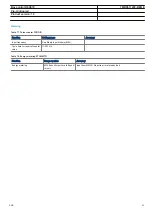
Page 64: ... Table 81 SPA communication protocol Function Value Protocol SPA Communication speed 300 1200 2400 4800 9600 19200 or 38400 Bd Slave number 1 to 899 Table 82 IEC60870 5 103 communication protocol Function Value Protocol IEC 60870 5 103 Communication speed 9600 19200 Bd Table 83 SLM LON port Quantity Range or value Optical connector Glass fibre type ST Plastic fibre type HFBR snap in Fibre optical ...

Page 65: ... 5 125 mm Plastic fibre 1 mm depending on optical budget calculation Table 85 Galvanic RS485 communication module Quantity Range or value Communication speed 2400 19200 bauds External connectors RS 485 6 pole connector Soft ground 2 pole connector Table 86 IEC 62439 3 Edition 1 and Edition 2 parallel redundancy protocol Function Value Protocol IEC 61850 8 1 Communication speed 100 Base FX Bay cont...

Page 66: ...ical distance 80 km 26 dB typical distance 110 km Optical connector Type ST Type FC PC Type FC PC Protocol C37 94 C37 94 implementation C37 94 implementation Data transmission Synchronous Synchronous Synchronous Transmission rate Data rate 2 Mb s 64 kbit s 2 Mb s 64 kbit s 2 Mb s 64 kbit s Clock source Internal or derived from received signal Internal or derived from received signal Internal or de...

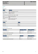
Page 67: ...19 10 kg 6U 3 4 x 19 15 kg 6U 1 1 x 19 18 kg Connection system Table 91 CT and VT circuit connectors Connector type Rated voltage and current Maximum conductor area Screw compression type 250 V AC 20 A 4 mm2 AWG12 2 x 2 5 mm2 2 x AWG14 Terminal blocks suitable for ring lug terminals 250 V AC 20 A 4 mm2 AWG12 Table 92 Binary I O connection system Connector type Rated voltage Maximum conductor area ...

Page 68: ...ally Table 95 GPS time synchronization module GTM Function Range or value Accuracy Receiver 1µs relative UTC Time to reliable time reference with antenna in new position or after power loss longer than 1 month 30 minutes Time to reliable time reference after a power loss longer than 48 hours 15 minutes Time to reliable time reference after a power loss shorter than 48 hours 5 minutes Table 96 GPS ...

Page 69: ...w level high level 1 3 Vpp 3 x low level max 9 Vpp Supported formats IRIG B 00x IRIG B 12x Accuracy 10μs for IRIG B 00x and 100μs for IRIG B 12x Input impedance 100 k ohm Optical connector Optical connector PPS and IRIG B Type ST Type of fibre 62 5 125 μm multimode fibre Supported formats IRIG B 00x PPS Accuracy 2μs Bay control REC670 1MRK511232 BEN E Pre configured Product version 1 2 ABB 69 ...

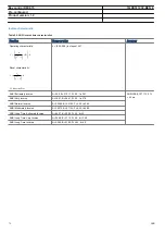
Page 70: ...I Extremely Inverse A 28 2 B 0 1217 P 2 0 tr 29 1 ANSI IEEE C37 112 5 40 ms ANSI Very inverse A 19 61 B 0 491 P 2 0 tr 21 6 ANSI Normal Inverse A 0 0086 B 0 0185 P 0 02 tr 0 46 ANSI Moderately Inverse A 0 0515 B 0 1140 P 0 02 tr 4 85 ANSI Long Time Extremely Inverse A 64 07 B 0 250 P 2 0 tr 30 ANSI Long Time Very Inverse A 28 55 B 0 712 P 2 0 tr 13 46 ANSI Long Time Inverse A 0 086 B 0 185 P 0 02 ...

Page 71: ...L V1 EN Reset characteristic PR TR t k I CR EQUATION1253 SMALL V1 EN I Imeasured Iset k 0 05 999 in steps of 0 01 A 0 005 200 000 in steps of 0 001 B 0 00 20 00 in steps of 0 01 C 0 1 10 0 in steps of 0 1 P 0 005 3 000 in steps of 0 001 TR 0 005 100 000 in steps of 0 001 CR 0 1 10 0 in steps of 0 1 PR 0 005 3 000 in steps of 0 001 Table 100 RI and RD type inverse time characteristics Function Rang...

Page 72: ...ALL V1 EN k 0 05 1 10 in steps of 0 01 Type C curve 3 0 480 32 0 5 0 035 æ ö ç è ø t k U U U EQUATION1438 SMALL V1 EN k 0 05 1 10 in steps of 0 01 Programmable curve æ ö ç è ø P k A t D U U B C U EQUATION1439 SMALL V1 EN k 0 05 1 10 in steps of 0 01 A 0 005 200 000 in steps of 0 001 B 0 50 100 00 in steps of 0 01 C 0 0 1 0 in steps of 0 1 D 0 000 60 000 in steps of 0 001 P 0 000 3 000 in steps of ...

Page 73: ...k t U U U EQUATION1432 SMALL V1 EN U Uset U Umeasured k 0 05 1 10 in steps of 0 01 Programmable curve é ù ê ú ê ú ê ú æ ö ê ú ç ëè ø û P k A t D U U B C U EQUATION1433 SMALL V1 EN U Uset U Umeasured k 0 05 1 10 in steps of 0 01 A 0 005 200 000 in steps of 0 001 B 0 50 100 00 in steps of 0 01 C 0 0 1 0 in steps of 0 1 D 0 000 60 000 in steps of 0 001 P 0 000 3 000 in steps of 0 001 Bay control REC6...

Page 74: ...37 SMALL V1 EN k 0 05 1 10 in steps of 0 01 Type C curve 3 0 480 32 0 5 0 035 æ ö ç è ø t k U U U EQUATION1438 SMALL V1 EN k 0 05 1 10 in steps of 0 01 Programmable curve æ ö ç è ø P k A t D U U B C U EQUATION1439 SMALL V1 EN k 0 05 1 10 in steps of 0 01 A 0 005 200 000 in steps of 0 001 B 0 50 100 00 in steps of 0 01 C 0 0 1 0 in steps of 0 1 D 0 000 60 000 in steps of 0 001 P 0 000 3 000 in step...

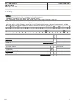
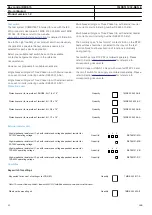
Page 75: ... 2 A30 A02C16D02E01F01H04K01M01 B1X0 DC KA B A6X0 ABFLURST ABF AD Using the code of each position 1 12 specified as REC670 1 2 2 3 3 3 3 3 3 3 3 3 4 5 6 7 7 8 9 9 9 10 10 10 10 10 10 10 10 10 10 10 10 10 10 11 11 11 11 11 11 12 12 1 2 3 4 5 6 7 8 9 REC670 10 11 12 Position SOFTWARE 1 Notes and Rules Version number Version no 1 2 Selection for position 1 Configuration alternatives 2 Notes and Rules...

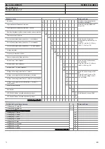
Page 76: ...n C30 Autorecloser 2 circuit breakers H 05 Autorecloser 1 1 2 circuit breakers H 06 Voltage control single transformer 1 objects H 11 Note H11 and H15 only in A30 B30 Note H16 and H18 only in C30 Note Only one voltage control can be ordered Voltage control eight parallel transformers 1 objects H 15 Voltage control single transformer 1 objects 2 control blocks H 16 Voltage control eight parallel tr...

Page 77: ...wer supply 24 60 VDC A 90 250 VDC B Selection for position 7 Human machine hardware interface 8 Notes and Rules Small size text only IEC keypad symbols A Medium size graphic display IEC keypad symbols B Note Required to give Raise Lower commands to the OLTC from IED670 via Voltage control VCTR function Medium size graphic display ANSI keypad symbols C Selection for position 8 Connection type for A...

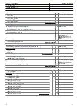
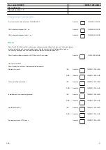
Page 78: ...0 250 VDC 50 mA E 1 E 1 E 1 E 1 E 1 E 1 E 1 E 1 E 1 E 1 E 1 E 1 E 1 BIMp 16 inputs RL24 30 VDC for pulse counting F F F F F F F F F F F F BIMp 16 inputs RL48 60 VDC for pulse counting G G G G G G G G G G G G BIMp 16 inputs RL110 125 VDC for pulse counting H H H H H H H H H H H H BIMp 16 inputs RL220 250 VDC for pulse counting K K K K K K K K K K K K IOM 8 inputs 10 2 output RL24 30 VDC L L L L L L...

Page 79: ...together with SLM Serial plastic and LON glass communication module B Serial and LON communication module glass C Serial IEC 60870 5 103 plastic interface F Serial IEC 60870 5 103 plastic glass interface G Serial IEC 60870 5 103 glass interface H Optical ethernet module 1 channel glass D Optical ethernet module 2 channel glass E Selection for position 12 Guidelines Carefully read and follow the se...

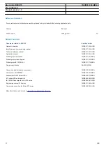
Page 80: ...ted documents for reference to corresponding documents RHGS 6 Case or RHGS 12 Case with mounted RTXP 24 and the on off switch for dc supply are ordered separately Please refer to Section Related documents for reference to corresponding documents Protection cover Protective cover for rear side of RHGS6 6U 1 4 x 19 Quantity 1MRK 002 420 AE Protective cover for rear side of terminal 6U 1 2 x 19 Quant...

Page 81: ...always included for each IED Rule Specify additional quantity of IED Connect CD requested Quantity 1MRK 002 290 AB User documentation Rule Specify the number of printed manuals requested Operator s manual IEC Quantity 1MRK 511 228 UEN ANSI Quantity 1MRK 511 228 UUS Technical reference manual IEC Quantity 1MRK 511 227 UEN ANSI Quantity 1MRK 511 227 UUS Installation and commissioning manual IEC Quan...

Page 82: ...1 231 BEN Product guide pre configured 1MRK 511 232 BEN Product guide IEC 61850 9 2 1MRK 511 219 BEN Sample specification SA2005 001280 Connection and Installation components 1MRK 513 003 BEN Test system COMBITEST 1MRK 512 001 BEN Accessories for 670 series IEDs 1MRK 514 012 BEN 670 series SPA and signal list 1MRK 500 092 WEN IEC 61850 Data objects list for 670 series 1MRK 500 091 WEN Engineering ...

Page 83: ...83 ...

Page 84: ...tact us ABB AB Substation Automation Products SE 721 59 Västerås Sweden Phone 46 0 21 32 50 00 Fax 46 0 21 14 69 18 www abb com substationautomation 1MRK511232 BEN E Copyright 2012 ABB All rights reserved ...

Reviews: