


A
B
C
E
D
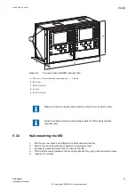
1
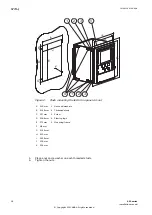
GUID-77659F5C-692A-4A14-BE37-623C09FCBF0C V1 EN-US
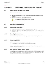
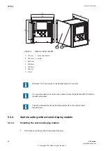
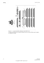
Figure 8:
Two rack mounted IEDs side by side
A 224 mm + 12 mm with ring-lug connector 1 Screws
B 25.5 mm
C 482.6 mm (19")
D 13 mm
E 265.9 mm (6U)
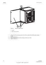
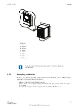
Make sure that the lower venting holes in the IED is not obstructed.
Check the allowed minimum bending radius from the optical cable
manufacturer.
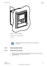
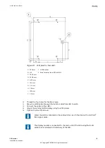
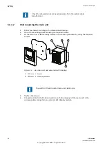
5.3.3
Wall mounting the IED
GUID-C6B7126A-6B94-4ECD-AA40-A7D84548F023 v4
1.
Drill four screw holes according to the dimensional drawing.
2.
Mount the mounting brackets using the required screws.
3.
Remove the plastic plugs from the side of the IED.
4.
Fit the IED securely between the mounting brackets by using the required screws.
5.
Tighten the screws.
1MRK 514 014-UEN A
Section 5
Mounting
650 series
23
Installation manual
© Copyright 2011 ABB. All rights reserved