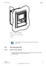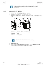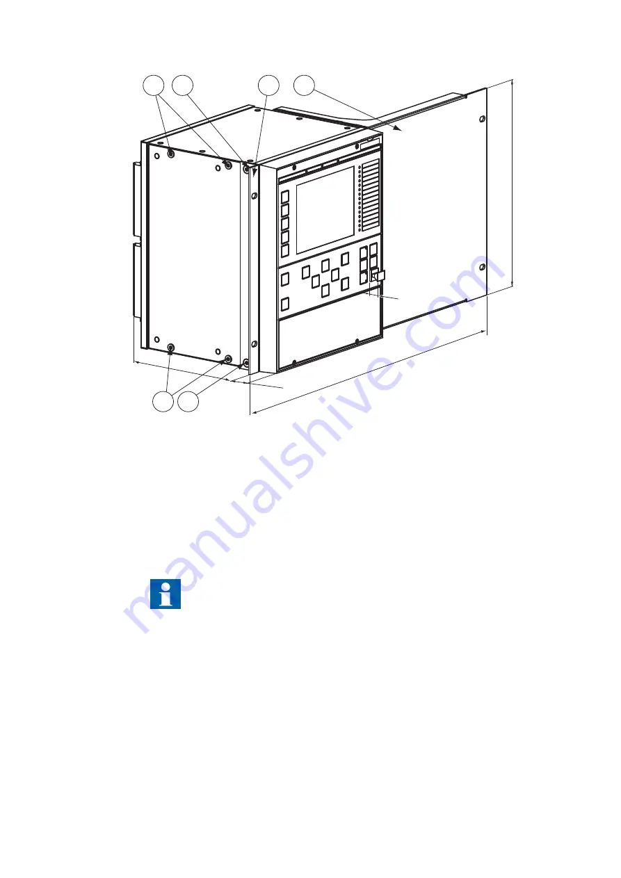
A
C
B
E
D
2
1
1
2
4
3
GUID-C8DC00E4-0416-424B-B1DF-432BE0AD40A6 V1 EN-US
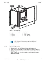
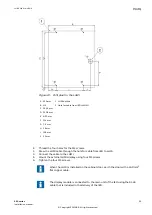
Figure 6:
Rack mounted IED
A 224 mm + 12 mm with ring-lug connector 1 Plastic plugs
B 25.5 mm
2 Screws
C 482.6 mm (19")
3 Left mounting bracket
D 265.9 mm (6U)
4 Right mounting bracket
E 13 mm
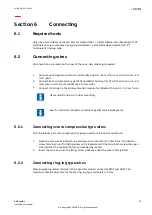
Check the allowed minimum bending radius from the optical cable
manufacturer.
5.3.2.2
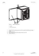
Rack mounting two IEDs
GUID-3E10B635-AB42-44B0-BDA2-9B7BDAC8FC8E v2
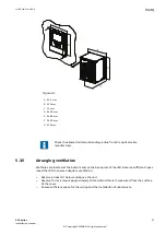
1.
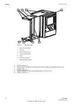
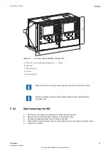
Remove the plastic plugs from the side of the case on both of the two IEDs.
2.
Locate the pins on the two middle mounting brackets to the holes on the sides of the
two IEDs.
3.
Mount the upper and lower mounting brackets to the two IEDs using the screws at the
required location.
Make sure that the lower venting hole on the IEDs line up with the venting hole in the
lower mounting bracket.
1MRK 514 014-UEN A
Section 5
Mounting
650 series
21
Installation manual
© Copyright 2011 ABB. All rights reserved


