Section 5
Mounting
5.1
Required tools
GUID-CBE5391F-3ECF-4D44-8454-BAD877684682 v1
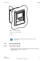
Use Torx TX10 and TX15 screwdrivers when attaching the mounting kits to the IED.
5.2
Checking environmental conditions and mounting
space
GUID-2AF46E8C-25B3-4606-A768-E4B70E3D6B0A v5
The mechanical and electrical environmental conditions at the installation site must be within
the limits described in the technical manual.
•
Avoid installation in dusty, damp places.
Avoid places susceptible to rapid temperature variations, powerful vibrations and shocks,
surge voltages of high amplitude and fast rise time, strong induced magnetic fields or
similar extreme conditions.
•
Check that sufficient space is available.
Sufficient space is needed at the front and rear of the IED to allow access to wires and
optical fibres and to enable maintenance and future modifications.
•
It is possible to add or replace flush mounted IEDs without excessive dismantling.
5.3
Mounting the IED
5.3.1
Flush mounting the IED
GUID-B41E6C2B-7F9B-4F60-8317-FFE67F0C7D70 v2
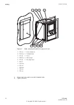
1.
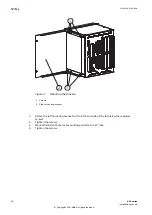
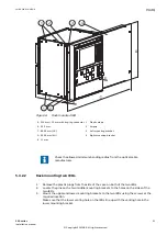
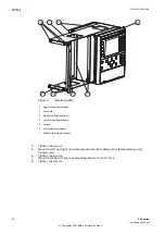
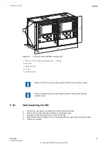
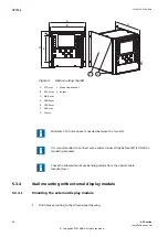
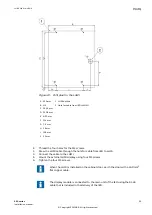
Make a panel cut-out and drill four holes according to the dimensional drawing.
2.
Locate the IED securely in the mounting frame using the required screws.
3.
Tighten the screws.
4.
Mount the IED with the mounting frame to the panel cut-out.
1MRK 514 014-UEN A
Section 5
Mounting
650 series
17
Installation manual
© Copyright 2011 ABB. All rights reserved


