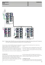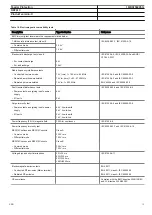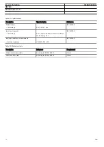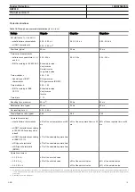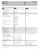
GUID-3DF1D683-0319-4A79-958D-252F4D745A96 V1 EN
Figure 3.
Substation feeder O/C and E/F protection, and substation busbar protection based on 610 series protection relays. The operate time
of the busbar protection has been speeded up using the principle of upstream interlocking.
The connection of the CTs to REF610 depends on the available
number and types of CTs in the feeder cubicle. Generally an
outgoing feeder is equipped with three phase current
transformers for high- and low-set overcurrent protection. The
residual current for the earth-fault protection can be derived
from the three phase currents. It can also be measured with a
ring-type cable current transformer, should the outgoing feeder
be a cable line and a sensitive earth-fault protection be
required.
Should the feeder cubicle be equipped with two phase current
transformers, REF610 can still be used for high- and low-set
overcurrent protection including phase discontinuity and phase
unbalance protection.
5. Measurement
The protection relay continuously measures the phase currents
and the residual current. Further the protection relay calculates
the thermal overload of the protected object, the phase
unbalance value, the one-minute demand value, the demand
value for a specified time frame and the maximum one-minute
demand value over a specified time frame.
The values measured can be accessed locally via the user
interface on the protection relay's front panel or remotely via the
serial communication interface of the protection relay.
6. Disturbance recorder
The protection relay is provided with a built-in battery backed-
up digital disturbance recorder for four analog signal channels
Feeder Protection
1MRS756295 G
REF610
Product version: C
6
ABB


