79
General fault criteria (GFC)
Chapter 4
Line distance
4.3
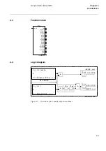
Function block
4.4
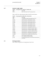
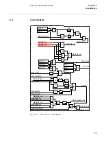
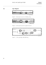
Logic diagram
Figure 32:
Detection of ph-E and ph-ph fault conditions
xx00000393.vsd
GFC--
GFC
BLOCK
TRIP
STFWL1
STFWL2
STFWL3
STFWPE
STRVL1
STRVL2
STRVL3
STRVPE
STNDL1
STNDL2
STNDL3
STNDPE
STFW1PH
STFW2PH
STFW3PH
STPE
STPP
STCND
GFC--BLOCK
&
&
t
10 ms
t
20 ms
&
t
15 ms
t
15 ms
GFC--STPE
GFC--STPP
IRELPE - cont.
IRELPP - cont.
3
⋅
I
0
≥
0.5
⋅
IMinOp
&
3
⋅
I
0
≥
(INRelease PE/100)
⋅
I
ph max
3
⋅
I
0
≤
0.2
⋅
I
r
or
3
⋅
I
0
≤
(INBlockPP/100)
⋅
I
ph max
en01000048.vsd
Summary of Contents for REL 501-C1 2.5
Page 1: ...Technical reference manual Line distance protection terminal REL 501 C1 2 5 ...
Page 2: ......
Page 26: ...14 Introduction to the technical reference manual Chapter 1 Introduction ...
Page 42: ...30 Technical data Chapter 2 General ...
Page 66: ...54 Blocking of signals during test BST Chapter 3 Common functions ...
Page 142: ...130 Time delayed overvoltage protection TOV Chapter 6 Voltage ...
Page 162: ...150 Autorecloser AR Chapter 9 Control ...
Page 174: ...162 Event function EV Chapter 10 Logic ...
Page 210: ...198 Serial communication Chapter 12 Data communication ...
Page 226: ...214 Serial communication modules SCM Chapter 13 Hardware modules ...
Page 230: ...218 Terminal diagrams Chapter 14 Diagrams Figure 87 REL 501 C1 with DC switch ...
Page 234: ...222 Terminal diagrams Chapter 14 Diagrams ...
Page 237: ......


