71
Automatic switch onto fault logic (SOTF)
Chapter 4
Line distance
2
Automatic switch onto fault logic (SOTF)
2.1
Application
The main purpose of the SOTFswitch-on-to-fault function is to provide high-speed tripping
when energizing a power line on to a short-circuit fault on the line.
Automatic initiating of the SOTF function using dead line detection can only be used when the
potential transformer is situated on the line-side of the circuit breaker. Initiation using dead line
detection is highly recommended for busbar configurations where more than one circuit breaker
at one line end can energize the protected line.
Generally, directional or non-directional overreaching distance or overcurrent protection func-
tions are used as the protection functions to be released for direct tripping during the activated
time. When line-side potential transformers are used, the use of non-directional protection zones
secures switch-on-to-fault tripping for fault situations where directional information can not be
established, for example, due to lack of polarizing voltage. Use of non-directional protection
also gives fast fault clearance when energizing a bus from the line with a short-circuit fault on
the bus.
2.2
Functionality
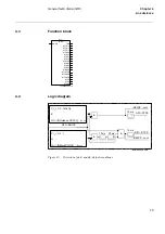
The SOTF function is a logical function built-up from logical elements. It is a complementary
function to the distance or overcurrent protection functions.
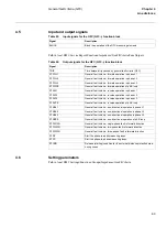
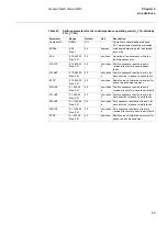
It is enabled for operation either by the close command to the circuit breaker, by a normally
closed auxiliary contact of the circuit breaker, or automatically by the dead line detection. Once
enabled, this remains active until one second after the enabling signal has reset. The protection
function(s) released for tripping during the activated time can be freely selected from the func-
tions included within the terminal. Pickup of any one of the selected protection functions during
the enabled condition will result in an immediate trip output from the SOTF function.
2.3
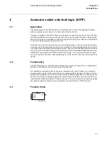
Function block
xx00000188.vsd
SOTF-
SOTF
BLOCK
NDACC
DLCND
BC
TRIP
Summary of Contents for REL 501-C1 2.5
Page 1: ...Technical reference manual Line distance protection terminal REL 501 C1 2 5 ...
Page 2: ......
Page 26: ...14 Introduction to the technical reference manual Chapter 1 Introduction ...
Page 42: ...30 Technical data Chapter 2 General ...
Page 66: ...54 Blocking of signals during test BST Chapter 3 Common functions ...
Page 142: ...130 Time delayed overvoltage protection TOV Chapter 6 Voltage ...
Page 162: ...150 Autorecloser AR Chapter 9 Control ...
Page 174: ...162 Event function EV Chapter 10 Logic ...
Page 210: ...198 Serial communication Chapter 12 Data communication ...
Page 226: ...214 Serial communication modules SCM Chapter 13 Hardware modules ...
Page 230: ...218 Terminal diagrams Chapter 14 Diagrams Figure 87 REL 501 C1 with DC switch ...
Page 234: ...222 Terminal diagrams Chapter 14 Diagrams ...
Page 237: ......


