93
Scheme communication logic (ZCOM)
Chapter 4
Line distance
6
Scheme communication logic (ZCOM)
6.1
Application
It is not possible to set an underreaching distance or overcurrent protection to cover the full
length of the line, and at the same time not to overreach for faults beyond the protected line. To
avoid overreaching, underreaching protection zones must always reach short of the remote end
of the line by some safety margin of 15-20%. The main purpose of the ZCOM scheme commu-
nication logic is to supplement the distance or overcurrent protection function such that fast
clearance of faults is also achieved at the line end for which the faults are on the part of the line
not covered by its underreaching zone. To accomplish this, one communication channel, capable
of transmitting an on/off signal, is required in each direction.
6.2
Functionality
The ZCOM function is a logical function built-up from logical elements. It is a supplementary
function to the distance or overcurrent protection, requiring for its operation inputs from the dis-
tance or overcurrent protection and the teleprotection equipment.
The type of communication-aided scheme to be used can be selected by way of the settings. The
ability to select which protection zone is assigned to which input of the ZCOM logic makes this
logic able to support practically any scheme communication requirements regardless of their ba-
sic operating principle. The outputs to initiate tripping and sending of the teleprotection signal
are given in accordance with the type of communication-aided scheme selected and the protec-
tion zone(s) which have operated.
When power line carrier communication channels are used, unblocking logic is provided which
uses the loss of guard signal. This logic compensates for the lack of dependability due to the
transmission of the command signal over the faulted line.
6.3
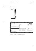
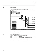
Function block
xx00000184.vsd
ZCOM-
ZCOM
BLOCK
CACC
CSUR
CSOR
CSBLK
CSNBLK
CR
CRG
TRIP
CS
CRL
LCG
Summary of Contents for REL 501-C1 2.5
Page 1: ...Technical reference manual Line distance protection terminal REL 501 C1 2 5 ...
Page 2: ......
Page 26: ...14 Introduction to the technical reference manual Chapter 1 Introduction ...
Page 42: ...30 Technical data Chapter 2 General ...
Page 66: ...54 Blocking of signals during test BST Chapter 3 Common functions ...
Page 142: ...130 Time delayed overvoltage protection TOV Chapter 6 Voltage ...
Page 162: ...150 Autorecloser AR Chapter 9 Control ...
Page 174: ...162 Event function EV Chapter 10 Logic ...
Page 210: ...198 Serial communication Chapter 12 Data communication ...
Page 226: ...214 Serial communication modules SCM Chapter 13 Hardware modules ...
Page 230: ...218 Terminal diagrams Chapter 14 Diagrams Figure 87 REL 501 C1 with DC switch ...
Page 234: ...222 Terminal diagrams Chapter 14 Diagrams ...
Page 237: ......

