


Power Automation and Protection Division
I.L. 40-201.9
REL 352 Version 1.00
4-1
4
Section 4. INSTALLATION, OPERATION AND MAINTENANCE
1.
SEPARATING THE INNER AND OUTERCHASSIS
!
CAUTION
It is recommended that the user of this equipment become acquainted with the
information in these instructions before energizing the REL 352 and associated
assemblies. Failure to observe this precaution may result in damage to the
equipment.
All integrated circuits used on the modules are sensitive to and can be damaged by
the discharge of static electricity. Electrostatic discharge precautions should be ob-
served when operating or testing the REL 352.
!
CAUTION
Use the following procedure when separating the inner chassis from the outer
chassis; failure to observe this precaution can cause personal injury, or undes-
ired tripping of outputs and component damage.
a.
Unscrew the front panel screws.
b. Remove the (optional) FT-14 covers if supplied (one on each side of the
REL 352).
c.
Open all FT-14 switches.
Do Not Touch the outer contacts of any FT-14 switch; they may be
energized.
d. Slide out the inner chassis.
e.
Close all FT-14 switches.
f.
Replace the FT-14 covers.
g. Reverse procedures above when replacing the inner chassis into the outer chassis.
2.
EXTERNAL WIRING
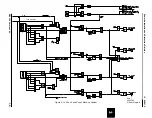
All external electrical connections pass thru the Backplate (Figure 4-1) on the outer chassis.
Seven DIN connectors (J11, J12, J13, JA1, JA2, JA3, JA4) allow for the removal of the inner
chassis from the outer chassis.
Electrical inputs to the Backplane module, which are routed either directly thru the Backplate or
thru the FT-14 switch to the Backplate include (
see Figure 4-1
):
• V
A
, V
B
, V
C
and V
N
• I
A
/I
AR
, I
B
/I
BR
, I
C
/I
CR
• Power Supply (Battery) Inputs
Primary (IBP, IBN)
Backup (2BP, 2BN)