I.L. 40-201.9
Power Automation and Protection Division
3-8
REL 352 Version 1.00
system. When this condition exists, all impedance measuring units will have their outputs
blocked.
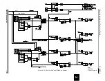
The simple logic is shown in Figure 3-13. This logic will detect one or two blown fuses, but will
fail to detect the unlikely failure of all three-phase fuses. The output of this logic will also ener-
gize the failure alarm relay.
8.2.
Loss of Current (LOI)
This logic is provided when the backup system is included in the relaying system.
The simple logic (shown in Figure 3-13) will detect the loss of one or two current inputs. The
output of this logic is only used to energize the failure alarm relay of REL 352.
8.3.
Reclosing Logic
REL 352 provides 3-phase Reclose Initiate contact outputs to be used with an external reclos-
ing relay. A Reclose Block (RB) contact output is also provided. The relaying system will block
the reclosing relay if reclosing into a permanent fault.
The Reclose Block Enable (RBEN) setting has the following options:
• NORB - No reclosing block
• ALRB - Reclose block for all fault types
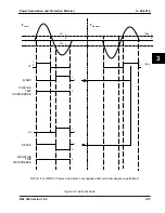
With 52b contact open (closed breaker) the sequence of operation is:
fault applied >> Pilot Trip >> Reclose initiate.
With 52b closed (open breaker) the sequence becomes:
52b closed >> fault applied >> Pilot Trip >> RIFT >> Reclose block.
Explanation:
Closing of 52b before applying fault enables the RIFT logic after 250 msec. The Pilot Trip ap-
pears to the relay to be on a first reclose rather than on initial trip, the RIFT prevents a “second”
reclose.
Initial trip is always without 52b (breaker closed), thus a reclose is initiated. When the breaker
opens on the initial trip, 52b closes and RIFT is armed in 250 msec.
When the breaker is closed on the first reclose 52b opens, but is held “on” logically for 500 msec
to the RIFT logic.
A Pilot Trip within that 500 msec is interpreted as having reclosed onto the same fault, and fur-
ther reclosing is blocked.
9.
FAULT LOCATOR
The REL 352 fault locator feature computes the magnitude and phase angle of the fault imped-
ance and the distance to the fault in both miles and kilometers. The fault impedance is calcu-
lated from the voltage and current phasors of the faulted phase(s). Thus, proper faulted phase
selection is essential for good fault locator results. The distance to the fault is computed by mul-
tiplying the imaginary part of the fault impedance times (VTR/CTR), the voltage transformer and
current transformer ratios, and dividing by the distance multiplier setting (XPUD). The imped-
ance calculations for the various fault types are:
Z
XG
=
V
XG
/ (I
X
+ KI
0
)


