Power Automation and Protection Division
I.L. 40-201.9
REL 352 Version 1.00
3-1
3
1.
INTRODUCTION
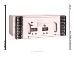
The REL 352 is a dual-microprocessor based, composite sequence filter, phase comparison
protection system. The REL 352 operates on the principles inherited from previous successful
phase comparison relaying systems; but, adapted and improved using numerical techniques.
The REL 352 is a communication channel dependent system optimized for operating with pow-
er line carrier equipment. Either ON-OFF or FSK (frequency shift) power line carrier equipment
can be used to interface with the REL 352.
It may also interface to other communication equipment that accepts a low frequency (60/50
Hz) modulation such as Single-Side-Band (SSB) PLC, Audio Tone or analog microwave.
The REL 352 is a high speed relaying system; suitable for application to any voltage level. Its
principle of operation makes it ideal for short lines and tapped lines with a power transformer,
where traditional distance protection fails.
An optional distance-type relaying system has been included to provide back-up for a loss of
communication channel. This back-up system is similar to a zone 2 and zone 3 distance units
and logic for a distance non-pilot relaying system. Phase and ground distance units are includ-
ed.
The phase comparison protection is inherently immune to systems’ swings and the relay will
block the tripping. However if trip is desired, blinders have been provided for detecting this con-
dition. OST (Out-of-Step Trip) is included. Trip under OST conditions may be selected via a re-
lay setting even when the channel is sound and the system is performing only phase
comparison.
An Overcurrent tripping function is also included in the relaying system. The “Highset” overcur-
rent function activates the trip outputs when the phase (IPH) or the ground (IGH) threshold units
detect currents above the settings. These units may be supervised (its recommended that they
be supervised) by the directional units. The phase units are supervised by FDOP and the
ground unit is supervised by FDOG. Of course the connection of external voltage transformers
to REL 352 is required to activate directional units.
The REL 352 also requires the connection to Voltage Transformers (vt’s) for distance protec-
tion, fault location, loss of potential and loss of current detection.
Because of the settings ranges available in the relaying system, it is possible to accommodate
different ct ratios at the terminals of the transmission line.
The REL 352 has the capability of communication channel propagation delay measurement,
which is very important for the correct operation of the relaying system. Once this delay has
been measured, it will be entered as a system setting. It is assumed that the channel delay in
a communication equipment will remain constant for the life of the transmission line and phase
comparison relaying system. If so desired, Periodic tests of the propagation delay can be easily
performed.
Section 3. APPLICATIONS AND ORDERING INFORMATION

