


REJ 523
Technical Reference Manual
ABB Substation Automation
Products and Systems
MRS750940-MUM
24
2)
The stage can be set out of operation with SGF switches. This state is indicated by
“---” on the LCD and by the reading “999” when parameters are read via the SPA bus.
Note!
The continuous current carrying capacity of the energizing inputs is 4.0 x I
n
.
Selector switchgroups SGF, SGB and SGR
Part of the settings and the selections of the operation characteristics of the relay in
various applications is made with selector switchgroups SG_. The switchgroups are
software-based and thus not physical switches to be found in the hardware of the
relay. The switches can be set one by one.
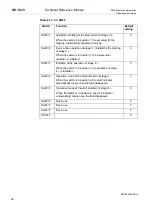
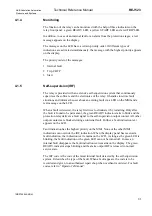
A checksum is used for verifying that the switches have been properly set. The figure
below shows an example of manual checksum calculation.
Switch
No
Position
Weighting
factor
Value
1
1
x
1
=
1
2
0
x
2
=
0
3
1
x
4
=
4
4
0
x
8
=
0
5
1
x
16
=
16
6
0
x
32
=
0
7
1
x
64
=
64
8
0
x
128
=
0
Checksum
SG_
∑
=
85
Figure 4.1.3.3-1 An example of calculating the checksum of a selector switchgroup
SG_.
When the checksum, calculated according to the example above, equals the checksum
read from the relay, the switches in the concerned switchgroup are properly set.
The following tables indicate the factory default settings of the switches and the
corresponding checksums.
Summary of Contents for REJ 523
Page 67: ......