U1>
U
a>b
a
b
t
tReset1
t
t1
AND
TR1
ST1
OFF
Delay
ON
Delay
IEC10000100-2-en.vsd
IEC10000100 V2 EN-US
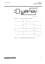
Figure 115:
Logic diagram for step 1, definite time delay, DT operation
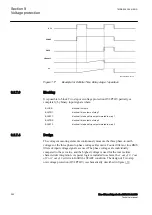
tReset1
U1>
START
TRIP
t1
IEC10000037-2-en.vsd
IEC10000037 V2 EN-US
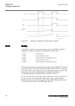
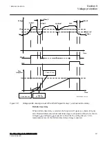
Figure 116:
Example for step 1, Definite Time Delay stage 1 reset
1MRK 505 394-UEN A
Section 9
Voltage protection
Line differential protection RED650 2.2 IEC
251
Technical manual
Summary of Contents for RED650
Page 1: ...RELION 650 SERIES Line differential protection RED650 Version 2 2 Technical manual...
Page 2: ......
Page 36: ...30...
Page 46: ...40...
Page 232: ...226...
Page 272: ...266...
Page 288: ...282...
Page 306: ...300...
Page 406: ...400...
Page 436: ...430...
Page 502: ...496...
Page 614: ...608...
Page 628: ...622...
Page 644: ...638...
Page 760: ...754...
Page 778: ...772...
Page 814: ...808...
Page 870: ...864...
Page 874: ...868...
Page 924: ...918...
Page 925: ...919...

