


protection. The maximum ground-fault current at the local source can be used to calculate
the value of ZN as V/(√3 · 3I
0
) Typically, the minimum ZNPol (3 · zero sequence source)
is set. Setting is in primary ohms.
When the dual polarizing method is used it is important that the product
INx>
· ZNpol is
not greater than 3V
0
. If so, there is a risk for incorrect operation for faults in the reverse
direction.
IPolMin
: is the minimum ground-fault current accepted for directional evaluation. For
smaller currents than this value the operation will be blocked. Typical setting is 5-10% of
IBase
.
VPolMin
: Minimum polarization (reference) residual voltage for the directional function,
given in % of
VBase
/√3.
IDirPU
: Operate residual current release level in % of
IBase
for directional comparison
scheme. The setting is given in % of
IBase
and must be set below the lowest
INx>
setting,
set for the directional measurement. The output signals, PUFW and PUREV can be used
in a teleprotection scheme. The appropriate signal should be configured to the
communication scheme block.
6.4.3.3
2nd harmonic restrain
If a power transformer is energized there is a risk that the current transformer core will
saturate during part of the period, resulting in a transformer inrush current. This will give
a declining residual current in the network, as the inrush current is deviating between the
phases. There is a risk that the residual overcurrent function will give an unwanted trip.
The inrush current has a relatively large ratio of 2nd harmonic component. This
component can be used to create a restrain signal to prevent this unwanted function.
At current transformer saturation a false residual current can be measured by the
protection. Also here the 2
nd
harmonic restrain can prevent unwanted operation.
2ndHarmStab
: The rate of 2nd harmonic current content for activation of the 2nd
harmonic restrain signal. The setting is given in % of the fundamental frequency residual
current.
HarmRestrainx
: Enable block of step
x
from the harmonic restrain function.
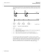
6.4.3.4
Line application example1
The Four step residual overcurrent protection EF4PTOC (51N/67N) can be used in
different ways. Below is described one application possibility to be used in meshed and
effectively grounded systems.
Section 6
1MRK 511 286-UUS A
Current protection
112
Application manual
Summary of Contents for REC650 ANSI
Page 1: ...Relion 650 series Bay control REC650 ANSI Application manual...
Page 2: ......
Page 26: ...20...
Page 66: ...Section 3 1MRK 511 286 UUS A REC650 setting examples 60 Application manual...
Page 71: ...IED IED ANSI05000460 V2 EN 1MRK 511 286 UUS A Section 4 Analog inputs 65 Application manual...
Page 82: ...76...
Page 92: ...86...
Page 170: ...164...
Page 176: ...170...
Page 274: ...268...
Page 288: ...282...
Page 350: ...344...
Page 369: ...363...


