


Operation Manual / Power2 850-M / 4 Product description
6 Periodic maintenance / 6.3 Cleaning turbine and nozzle ring during
operation
© Copyright 2019 ABB. All rights reserved.
HZTL4061_EN
Rev.B
June 2019
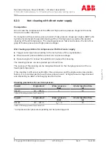
Repetitions of wet cleaning
The repeating of cleaning cycles one immediately after the other must be avoided as this
can lead to excessive mechanical stress, hence reducing the operating life of the compon-
ents.
The action of the cleaning water on the peripheral units (such as boiler) must be clarified by
the operator.
Draining the gas outlet casing of the low-pressure stage
The following points must be observed with regard to draining the gas outlet casing:
¡
The exhaust gas temperature downstream of the low-pressure stage drops drastically
during cleaning (typical gas outlet temperatures during cleaning: 50 ... 150 °C).
¡
Depending on the engine load, the drainage can take place through the drain pipe. This
drainage may occur after 2 … 3 minutes or not at all.
¡
If the drainage of the gas outlet casing is omitted, the low-pressure stage speed and/or
the gas inlet temperature must be monitored during the cleaning process. If the load is
too low, water can collect in the gas outlet casing. Indications for this are a sudden
severe drop in the low-pressure stage speed or a very large increase in the gas inlet tem-
perature. In such cases, the cleaning operations must be stopped and the cleaning cycle
restarted with reduced water pressure or higher engine load.
Calculation of the gas pulse
The pulse I
G
for the flow of gas is calculated according to the following relationship:
p
G
is the density of the exhaust gas at the inlet into the gas inlet casing.
V
G
corresponds to the flow rate at the nozzle ring inlet.
A
NR
corresponds to a reference surface of the flow channel at the nozzle ring inlet. The values
are specified in the following table.
Power2
Surface of the flow channel at the
nozzle ring inlet of the HP turbine stage
[m
2
]
Surface of the flow channel at the
nozzle ring inlet of the LP turbine stage
[m
2
]
850
0.031
0.068
Table 14: Surface of the flow channel
Page
34
/
51


