2101510 Rev. AG
Page 3–29
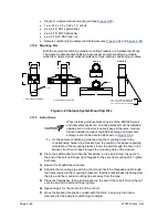
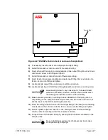
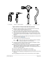
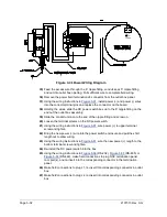
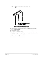
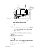
Figure 3-28 Power Communication Outlet Box Assembly
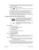
4)
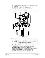
Moving the assembly clockwise, screw the nipple fitting into the hub until the
assembly is tight and hanging straight down at a 180
˚
.
5)
Feed the other end of the wire bundle through the flexible cable assembly,
beginning at end with the sealing gasket, until threads meet the conduit seal.
6)
Rotate the flexible cable assembly clockwise, screwing threads into the conduit
seal until tight. For explosion-proof installations, a minimum of 5 threads must be
engaged.
7)
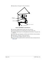
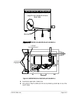
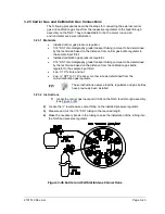
Feed wires through the small hole located near the sample boot in the lower front
of the enclosure (see
.
8)
Remove the cover from the outlet box assembly.
Remove the elbow cap on the outlet box assembly to facilitate
feeding the wrapped wire around the elbow.
9)
Feed wires through the outlet box elbow and out past the wiring panel, moving
the assembly up to the threaded end of the cable.
10)
Begin threading the outlet box assembly onto the end of flexible cable assembly,
rotating the entire outlet box assembly clockwise until snug and in a vertical
(360
˚
) position. For explosion-proof installations, the final assembly must have a
minimum of 5 threads engaged.
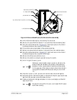
11)
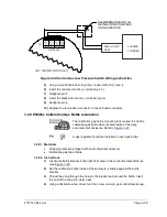
Locate the support bracket mounting holes on the enclosure.
12)
Place the split washer, then a flat washer on the end of each screw.
13)
Insert the screw through the mounting bracket and into the hole on the side of the
enclosure.
14)
Using a phillips point screwdriver, start the screw into hole, but do not tighten.
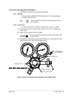
DC POWER SWITCH
INTERNAL NGC CONNECTION ASSEMBLY
FLEXIBLE CABLE ASSEMBLY
OUTLET BOX ASSEMBLY

