background image

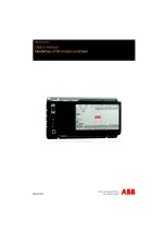
NextMove e100 motion controller

Summary of Contents for NextMove e100

Page 1: ...NextMove e100 motion controller ...

Page 2: ......

Page 3: ...og I O 4 3 4 2 1 Analog inputs 4 3 4 2 2 Analog outputs 4 5 4 3 Digital I O 4 7 4 3 1 Digital inputs 4 7 4 3 2 Digital outputs and relay 4 12 4 3 3 Stepper control outputs models NXE100 16xxDx 4 14 4 3 4 Stepper control outputs models NXE100 16xxSx 4 15 4 4 Other I O 4 16 4 4 1 Encoder inputs 0 2 4 16 4 4 2 Node ID selector switches 4 18 4 5 USB and serial communication 4 21 4 5 1 USB port 4 21 4 ...

Page 4: ...0 5 3 2 Starting Mint WorkBench 5 11 5 4 Configuring axes 5 13 5 4 1 Local axes remote axes and profilers 5 13 5 4 2 Configuring remote axes 5 14 5 4 3 Configuring local axes 5 16 5 4 4 Selecting a scale 5 17 5 4 5 Setting the drive enable output optional local axes only 5 19 5 4 6 Testing the drive enable output 5 21 5 5 Local stepper axis testing 5 22 5 5 1 Testing the output 5 22 5 6 Local serv...

Page 5: ...Motor control 6 4 6 2 6 Mint WorkBench 6 5 6 2 7 Ethernet 6 6 6 2 8 CANopen 6 6 7 Specifications 7 1 Introduction 7 1 7 1 1 Input power 7 1 7 1 2 Analog inputs 7 1 7 1 3 Analog outputs 7 1 7 1 4 Digital inputs 7 2 7 1 5 Digital outputs 7 2 7 1 6 Relay output 7 2 7 1 7 Stepper control outputs 7 3 7 1 8 Encoder inputs 7 3 7 1 9 Serial port 7 3 7 1 10 Ethernet interface 7 3 7 1 11 CAN interface 7 4 7...

Page 6: ...uidelines C 1 Outline C 1 C 1 1 CE marking C 1 C 1 2 Compliance with the EMC Directive C 1 C 1 3 Use of CE compliant components C 2 C 1 4 EMC installation suggestions C 2 C 1 5 Wiring of shielded screened encoder cables C 2 C 2 Marks C 2 C 2 1 RoHS Compliance C 2 C 2 2 China RoHS marking C 3 C 2 3 WEEE notice C 3 ...

Page 7: ... implied warranties of fitness for any particular purpose The information in this document is subject to change without notice ABB assumes no responsibility for any errors that may appear in this document Mint is a registered trademark of Baldor a member of the ABB group Windows XP Windows Vista and Windows 7 are registered trademarks of the Microsoft Corporation UL and cUL are registered trademar...

Page 8: ...h cardiac pacemakers internal cardiac defibrillators neurostimulators metal implants cochlear implants hearing aids and other medical devices To avoid risk stay away from the area surrounding a motor and its current carrying conductors The stop input to this equipment should not be used as the single means of achieving a safety critical stop Drive disable motor disconnect motor brake and other mea...

Page 9: ... axes on board plus external axes over the Ethernet POWERLINK connection Point to point moves software cams and gearing complex path control splines etc 20 general purpose digital inputs software configurable as level or edge triggered 12 general purpose digital outputs and 1 relay output 2 differential analog inputs with 12 bit resolution 4 single ended analog outputs with 12 bit resolution USB 1...

Page 10: ...l installation of the NextMove e100 The following sections require knowledge of the low level input output requirements of the installation and an understanding of computer software installation If you are not qualified in these areas you should seek assistance before proceeding Note You can check that you have the latest firmware and Mint WorkBench releases by visiting the website www abbmotion c...

Page 11: ...t conforms to the storage humidity and temperature specifications shown in section 3 1 1 2 2 1 Identifying the catalog number Different models of NextMove e100 are available As a reminder of which product has been installed it is a good idea to write the catalog number in the space provided below A description of the catalog numbers are shown in the following table Note The x represents a letter i...

Page 12: ...mation International Users and Manufacturers Group e V CTRL E on the PC keyboard press Ctrl then E at the same time DAC Digital to Analog Converter DS301 CiA CANopen Application Layer and Communication Profile DS401 CiA Device Profile for Generic I O Devices DS402 CiA Device Profile for Drives and Motion Control DS403 CiA Device Profile for HMIs EDS Electronic Data Sheet EMC Electromagnetic Compat...

Page 13: ...equipment or directly below water steam pipes Avoid locating the NextMove e100 in the vicinity of corrosive substances or vapors metal particles and dust The safe operation of this equipment depends upon its use in the appropriate environment The following points must be considered The NextMove e100 is designed to be mounted indoors permanently fixed and located The NextMove e100 must be secured b...

Page 14: ...cal surface Orientation must be as shown in Figure 1 with the two slots in the metal carrier heat sink assembly at the bottom Figure 1 Package dimensions There must be at least 20 mm 0 8 in clearance between the NextMove e100 and neighboring equipment to allow sufficient cooling by natural convection Remember to allow additional space around the edges to accommodate the mating connectors and assoc...

Page 15: ...used by a normal office PC is not suitable for direct communication with the NextMove e100 It is recommended to install a separate dedicated Ethernet adapter in the PC which can be configured for use with the NextMove e100 See section 5 1 7 A USB cable or RS485 422 serial cable Your PC operating system user manual might be useful if you are not familiar with Windows Minimum specification Processor...

Page 16: ...3 4 Basic Installation MN1941WEN ...

Page 17: ...puts I O Input Output DIN Digital Input DOUT Digital Output AIN Analog Input AOUT Analog Output Common electrical connections use the following abbreviations AGND Analog ground Used by the analog input and output circuits USR V User power supply V Provides power to the digital outputs USR GND User power supply ground Return connection for the user power supply CREFx Common reference The common con...

Page 18: ...REF2 CREF1 CREF0 USR V USR GND USR V DOUT11 DOUT10 DOUT9 DOUT8 Shield DIR3 DIR3 STEP3 STEP3 DGND Shield DIR2 DIR2 STEP2 STEP2 DGND Shield DIR1 DIR1 STEP1 STEP1 DGND Shield DIR0 DIR0 STEP0 STEP0 DGND 24 V 0 V For model NXE100 16xxSx Shield DIR3 5V out STEP3 NC DGND Shield DIR2 5V out STEP2 NC DGND Shield DIR1 5V out STEP1 NC DGND Shield DIR0 5V out STEP0 NC DGND Tightening torque for terminal block...

Page 19: ...uts pass through a differential buffer and second order low pass filter with a cut off frequency of approximately 1 kHz Both inputs are normally sampled at 2 kHz However an input can be disabled by setting ADCMODE to 4 _acOFF With one input disabled the remaining input will be sampled at 4 kHz In Mint analog inputs can be read using the ADC keyword See the Mint help file for full details of ADC AD...

Page 20: ... Figure 4 Typical input circuit to provide 0 10 V approx input from a 24 V source X12 1 2 3 X12 1 2 3 AIN0 AIN0 AIN0 GND AIN0 ADC 0 AIN0 ADC 0 Differential connection Single ended connection 2 1 X12 3 AIN0 ADC 0 24 V DC 1 5 kΩ 0 25 W 1 kΩ 0 25 W potentiometer 0V ...

Page 21: ...ion 5 4 3 All of the outputs may be used as general purpose analog outputs provided they have not been assigned to an axis see the DAC keyword in the Mint help file The analog outputs may be used to drive loads of 4 kΩ or greater Shielded twisted pair cable should be used The shield connection should be made at one end only Figure 5 Analog output Demand0 shown Figure 6 Analog output typical connec...

Page 22: ...g output typical connection to a Baldor FlexDriveII Flex DriveII or MintDriveII 2 3 1 2 1 X1 X13 AIN0 AIN0 NextMove e100 AGND Demand0 Shield Connect overall shield at one end only Servo amplifier 10 VDC demand Input FlexDriveII servo amplifier ...

Page 23: ...00 or e150 drive over EPL e g MotiFlex e100 a controlled node the axis home switch input must be wired to the drive not the NextMove e100 This is because the NextMove e100 only triggers the homing sequence which is then performed entirely by the drive It is therefore the drive which must receive the home switch input signal otherwise it will not be able to complete its homing routine Similarly it ...

Page 24: ...o be performed as a result of fast position inputs becoming active See the Mint help file for details Figure 8 Fast interrupt digital input DIN3 shown Digital inputs DIN0 to DIN3 use CREF0 as their common connection Note The fast inputs are particularly sensitive to noise so inputs must use shielded twisted pair cable Do not connect mechanical switches relay contacts or other sources liable to sig...

Page 25: ... triggering pulse must have a duration of at least 1 ms one software scan to guarantee acceptance by Mint The use of shielded cable for inputs is recommended 4 3 1 5 DIN12 DIN19 Digital inputs DIN12 to DIN19 have the same electrical specification as DIN4 11 except that they use CREF2 as their common connection Figure 10 General purpose digital input DIN19 shown 6k2 TLP281 100R 1 9 10 X9 NextMove e...

Page 26: ...IN0 to DIN3 Using a mechanical switch relay contacts or other source liable to signal bounce could cause unwanted multiple triggering Figure 13 Digital input typical connections from an ABB MicroFlex e100 8 9 TLP281 X9 6k2 100R NextMove e100 CREF1 DIN4 User supply 24V User supply GND 8 9 TLP281 X9 6k2 100R NextMove e100 CREF1 DIN4 User supply 24V User supply GND 8 9 TLP 127 TLP281 11 1 X9 X3 6k2 1...

Page 27: ...e 14 Digital input typical connections from a Baldor FlexDriveII Flex DriveII or MintDriveII 8 9 NEC PS2562L 1 X1 6 18 X9 TLP281 6k2 100R NextMove e100 CREF1 DIN4 User supply 24V User supply GND USR V DOUT0 FlexDriveII equipment output ...

Page 28: ... maximum continuous current of 350 mA but if other outputs are being used the total current must not exceed 500 mA The maximum allowable power dissipation for the UDN2982 driver is 1 5 W If an output is used to drive an inductive load such as a relay a suitably rated diode must be fitted across the relay coil observing the correct polarity The use of shielded cable is recommended Figure 15 Digital...

Page 29: ...nected to REL NO In the event of an error or power loss the relay is de energized and REL COM is connected to REL NC For control purposes the relay is considered to be another digital output DOUT12 and can be controlled directly using the Mint OUT or OUTX keywords The relay can be configured as the global error output by setting GLOBALERROROUTPUT to 12 See the Mint help file Figure 16 Relay connec...

Page 30: ... 5 MHz Values less than 60 Hz will produce no output see the Mint help file The DS26LS31 drivers are static sensitive devices Take appropriate ESD precautions when handling the NextMove e100 When connecting the outputs to single ended inputs as shown in Figures 17 and 18 do not connect the STEPx or DIRx outputs to ground leave them unconnected Figure 17 Stepper output typical connection to an ABB ...

Page 31: ...3 drivers are static sensitive devices Take appropriate ESD precautions when handling the NextMove e100 A 5 V supply is provided on connectors X2 and X3 for powering external circuits as shown in Figure 19 The same 5 V supply is also present on connectors X5 X6 and X7 for powering encoders Ensure that the total combined current demand of all 5 V outputs does not exceed 600 mA It is usually necessa...

Page 32: ...eset 4 4 1 1 Encoder input frequency The maximum encoder input frequency is affected by the length of the encoder cables The theoretical maximum frequency is 20 million quadrature counts per second This is equivalent to a maximum frequency for the A and B signals of 5 MHz However the effect of cable length is shown in Table 1 The maximum recommended cable length is 30 5 m 100 ft Location X5 X6 X7 ...

Page 33: ...96 120R 10k 1 6 4 5 1 6 X7 MAX3096 120R 2 7 2 7 MAX3096 120R 3 8 3 8 10k 10k X5 5 Twisted pair Twisted pair Twisted pair NextMove e100 to CPU to CPU to CPU MicroFlex FlexDriveII Flex DriveII MintDriveII encoder output Connect overall shield to connector backshells shield connections DGND DGND CHA CHA CHB CHB CHZ CHZ CHA CHA CHB CHB CHZ CHZ Vcc Vcc Vcc Shield ...

Page 34: ... 0 3 67 4 3 131 8 3 195 C 3 4 0 4 68 4 4 132 8 4 196 C 4 5 0 5 69 4 5 133 8 5 197 C 5 6 0 6 70 4 6 134 8 6 198 C 6 7 0 7 71 4 7 135 8 7 199 C 7 8 0 8 72 4 8 136 8 8 200 C 8 9 0 9 73 4 9 137 8 9 201 C 9 10 0 A 74 4 A 138 8 A 202 C A 11 0 B 75 4 B 139 8 B 203 C B 12 0 C 76 4 C 140 8 C 204 C C 13 0 D 77 4 D 141 8 D 205 C D 14 0 E 78 4 E 142 8 E 206 C E 15 0 F 79 4 F 143 8 F 207 C F 16 1 0 80 5 0 144 ...

Page 35: ...2 7 103 6 7 167 A 7 231 E 7 40 2 8 104 6 8 168 A 8 232 E 8 41 2 9 105 6 9 169 A 9 233 E 9 42 2 A 106 6 A 170 A A 234 E A 43 2 B 107 6 B 171 A B 235 E B 44 2 C 108 6 C 172 A C 236 E C 45 2 D 109 6 D 173 A D 237 E D 46 2 E 110 6 E 174 A E 238 E E 47 2 F 111 6 F 175 A F 239 E F 48 3 0 112 7 0 176 B 0 240 F 0 49 3 1 113 7 1 177 B 1 241 F 1 50 3 2 114 7 2 178 B 2 242 F 2 51 3 3 115 7 3 179 B 3 243 F 3 ...

Page 36: ...ds from the manager node Node ID 240 F0 causes the node to become the manager node a node that will control the timing and issue commands to controlled nodes There must only be one manager node on the network Node IDs 241 255 F1 FF are reserved for special purposes and cannot be used For all other communication channels such as CANopen USB and serial the node ID is set in software Each channel can...

Page 37: ...ps If it is connected to a faster USB 2 0 480 Mbps or USB 3 0 5 Gbps host PC or hub communication speed will remain at the USB 1 1 specification of the NextMove e100 Ideally the NextMove e100 should be connected directly to a USB port on the host PC If it is connected to a hub shared by other USB devices communication could be affected by the activity of the other devices The maximum recommended c...

Page 38: ... bit 8 data bits 1 stop bit No parity Hardware handshaking lines RTS and CTS must be connected The RS232 port is configured as a DCE Data Communications Equipment unit so it is possible to operate the controller with any DCE or DTE Data Terminal Equipment Full duplex transmission with hardware handshaking is supported Only the TXD RXD and 0V GND connections are required for communication but since...

Page 39: ...in Mint WorkBench Figure 23 4 wire RS422 multi drop connections Each transmit receive TX RX network requires a termination resistor at the final RX connection but intermediate devices must not be fitted with termination resistors An exception is where repeaters are being used which may correctly contain termination resistors Termination resistors are used to match the impedance of the load to the ...

Page 40: ...nnecting serial Baldor HMI Operator Panels Serial Baldor HMI Operator Panels use a 15 pin male D type connector marked PLC PORT but the NextMove e100 Serial connector uses a 9 pin male D type connector The NextMove e100 may be connected as shown in Figure 24 Figure 24 RS232 cable wiring Alternatively the Baldor HMI panel may be connected using RS485 422 as shown in Figure 25 Figure 25 RS485 422 ca...

Page 41: ...sent to the controller over the Ethernet network When operating in standard Ethernet mode TCP IP cannot be used to communicate with a controller on a daisy chained network This is due to cumulative timing errors caused by each controller s internal hub It is necessary to connect the host PC to the controller either directly or via a switch or hub as shown in Figure 26 A switch is preferable to a h...

Page 42: ... providing two ports for connection to other equipment This allows nodes to be connected as a daisy chain network Each node introduces a delay of approximately 500 ns so in time critical applications this could limit the number of nodes in a chain Propagation delays due to cabling should also be considered Hubs may be used if necessary but Ethernet switches must not be used in EPL networks as thei...

Page 43: ... because many Ethernet devices including hubs and all ABB EPL products incorporate Auto MDIX switching technology which automatically compensates for the wiring of the straight cable However if other manufacturer s EPL nodes are included in the EPL network crossover cables should be used as recommended by the Ethernet POWERLINK Standardization Group EPSG The NextMove e100 Ethernet interface is gal...

Page 44: ...over CAN can only be achieved with a suitable wiring scheme so the following points should be observed The two wire data bus line may be routed parallel twisted and or shielded depending on EMC requirements ABB recommends a twisted pair cable with the shield screen connected to the connector backshell in order to reduce RF emissions and provide immunity to conducted interference The bus must be te...

Page 45: ... 6 0 V of the CAN connector From this supply an internal voltage regulator provides the 5 V at 100 mA required for the isolated CAN circuit A connector such as the Phoenix Contact SUBCON PLUS F3 Phoenix part 2761871 provides a 9 pin D type female connector with easily accessible terminal block connections CAN cables supplied by ABB are category 5 and have a maximum current rating of 1 A so the max...

Page 46: ...rd party CANopen master device Up to 126 CANopen nodes node IDs 2 to 127 can be added to the network by a NextMove e100 Manager node using the Mint NODESCAN keyword If successful the nodes can then be connected to using the Mint CONNECT keyword Any network and node related events can then be monitored using the Mint BUS1 event Note All CAN related Mint keywords are referenced to CANopen using the ...

Page 47: ...llow the NextMove e100 and a single axis servo amplifier to work together Details of the connector pins are shown in Table 2 Figure 31 Example minimum system wiring 24V 0V X13 X5 X1 1 2 3 9 10 X12 USB Host PC NextMove e100 Servo amplifier axis 0 Common earth ground 24 V control supply Demand Demand Enable Gnd Encoder output from drive or motor USB connection ...

Page 48: ...2 24 V Control supply 24 V input X5 Encoder0 Encoder0 feedback input Encoder output X12 9 REL NO Normally open relay contact closed to enable drive Enable 24 V 10 REL COM Common relay connection Enable GND X13 1 Demand0 Demand output 0 Demand 2 AGND Analog GND Demand 3 Shield Shield connection Do not connect Table 2 Connector details for minimum system wiring shown in Figure 31 ...

Page 49: ...w the NextMove e100 and a single axis EPL servo amplifier e g MicroFlex e100 to work together Details of the connector pins are shown in Table 3 Figure 32 Example minimum system wiring 24V 0V X1 9 10 X12 USB Host PC NextMove e100 Common earth ground 24 V control supply Drive Enable USB connection Ethernet Remote EPL servo amplifier MicroFlex e100 E1 E2 Ethernet ...

Page 50: ... labeled differently X1 1 0 V Control supply ground 2 24 V Control supply 24 V input X12 9 REL NO Normally open relay contact closed to enable drive Drive Enable 10 REL COM Common relay connection Drive Enable E1 E2 Ethernet Ethernet EPL communication E1 E2 Table 3 Connector details for minimum system wiring shown in Figure 32 ...

Page 51: ...Ethernet ports You cannot connect an ordinary office PC to the NextMove e100 without first altering the PC s Ethernet adapter configuration However if you have installed a second Ethernet adapter dedicated for use with the NextMove e100 then this adapter s configuration can be altered without affecting the PC s office Ethernet connection If you are unsure about making changes to your PC s Ethernet...

Page 52: ...e previous sections you should have now connected the power sources inputs and outputs and the USB serial or Ethernet cable linking the PC to the NextMove e100 5 1 4 Preliminary checks Before you apply power for the first time it is very important to verify the following Disconnect the load from the motor until instructed to apply a load Inspect all power connections for accuracy workmanship and t...

Page 53: ... and newer no interaction should be necessary 2 When installation is complete a new Motion Control category will be listed in Windows Device Manager The NextMove e100 is now ready to be configured using Mint WorkBench Note If the NextMove e100 is later connected to a different USB port on the host computer Windows may report that it has found new hardware Either install the driver files again for ...

Page 54: ...work Connections 2 In the Network Connections Window right click the Local Area Connection entry for the required Ethernet adapter and choose Properties 3 In the Local Area Connection Properties dialog in the This connection uses the following items list select the Internet Protocol TCP IP entry and click Properties 4 In the Internet Protocol TCP IP Properties dialog on the General tab make a note...

Page 55: ...g once on a controller s name causes various options to be displayed in the information pane Double clicking on a controller s name launches an instance of Mint WorkBench that is automatically connected to the controller Application View allows the layout and organization of controllers in your machine to be modelled and described on screen Controllers can be dragged onto the Application View icon...

Page 56: ...rk visibility provided by Mint Machine Center RS232 RS485 422 Host PC Mint Machine Center Mint WorkBench Mint WorkBench Mint WorkBench Mint WorkBench Mint WorkBench MicroFlex e100 MicroFlex e100 NextMove e100 MintDriveII MintDriveII USB Ethernet USB ...

Page 57: ...s selected In the information pane click Scan 3 When the search is complete click once on NextMove e100 in the controller pane to select it then double click to open an instance of Mint WorkBench The NextMove e100 will be already connected to the instance of Mint WorkBench ready to configure Go straight to section 5 4 to continue the configuration in Mint WorkBench ...

Page 58: ...ctor switches are not set to F0 Although F0 is the correct node ID to make the NextMove e100 an EPL manager node the remote nodes have not yet been configured for EPL operation so will be ignored if the NextMove e100 is operating as a manager node In this example communications will use standard Ethernet not EPL 1 In the controller pane ensure that Host is selected In the information pane click Sc...

Page 59: ...d from the menu or by clicking a button use whichever you prefer Most buttons include a tool tip hold the mouse pointer over the button don t click and its description will appear Mint WorkBench can be started directly from the Windows Start menu or automatically by double clicking on a controller in the MMC s controller pane see section 5 2 1 Figure 35 The Mint WorkBench software Menu system Tool...

Page 60: ... an alphabetic list of all topics in the file and allows you to search for them by name The Search tab allows you to search for words or phrases appearing anywhere in the help file Many words and phrases are underlined and highlighted with a color normally blue to show that they are links Just click on the link to go to an associated keyword Most keyword topics begin with a list of relevant See Al...

Page 61: ...ave already used MMC to start an instance of Mint WorkBench then the following steps are unnecessary Go to section 5 4 to continue configuration 1 On the Windows Start menu select Programs Mint WorkBench Mint WorkBench 2 In the opening dialog box click Start New Project ...

Page 62: ...n the search is complete click NextMove e100 in the list to select it and then click Select Note If the NextMove e100 is not listed check the USB or serial cable between the NextMove e100 and the PC Check that the NextMove e100 is powered correctly and has completed its startup sequence indicated by the slowly flashing green Status LED Click Scan to re scan the ports 4 A dialog box may be displaye...

Page 63: ...e100 s edge connectors STEP DIR for stepper axes Demand and ENC for servo axes 5 4 1 2 Remote axes In addition to the 7 local axes the NextMove e100 can also control several remote axes Remote axes are drive amplifiers such as MicroFlex e100 connected to the NextMove e100 over the EPL connection There are three ways for the NextMove e100 the manager node to control a remote axis a controlled node ...

Page 64: ...is used to assign the node IDs and axis numbers 1 In the Toolbox click the System Configuration icon 2 On the EPL Devices page click Add Device 3 In the central drop down box select the type of EPL device for example MicroFlex e100 At the top of the window select the node ID of the EPL device The node ID allows the NextMove e100 to uniquely identify the EPL device on the network Click OK The Resou...

Page 65: ...100 contains a statement such as MOVER 5 20 the NextMove e100 will send a demand to the remote axis 5 to move 20 units 6 Click Close in the Resource Mapping window The EPL device is now listed in the EPL Devices page Note As shown in the preceding example the EPL device s assigned axis number 5 and node ID 8 do not have to be the same However in small networks it may be beneficial to assign the sa...

Page 66: ...Axis to display the Configure Local Axis window 4 In the Configure Local Axis window select one of the available axis numbers This is the axis number that will be assigned to the local axis To create a servo axis Select the Servo radio button In the Servo frame choose which encoder input s will be used as the feedback input s and which DAC output Demandx output will be used for the axis To create ...

Page 67: ...of steps per revolution Typically this would be 200 for a motor with a 1 8 step angle or 400 if driven in half step mode By setting a SCALEFACTOR of 200 or 400 if driven in half step mode the user unit becomes revolutions In applications involving linear motion a suitable value for SCALEFACTOR would allow commands to express values in linear distance for example millimeters inches or feet When set...

Page 68: ... tool Note The parameter list also contains entries for PosScaleFactor VelScaleFactor and AccelScaleFactor These parameters are provided to comply with the CANopen DS402 Device Profile for Drives and Motion Control which specifies separate scaling for position velocity and acceleration Each can be set to different values so that for example position could be specified in mm velocity in m s2 and ac...

Page 69: ...t can be either the relay or a digital output For a remote axis e g MicroFlex e100 a physical drive enable connection from the NextMove e100 may not be required The remote axis drive enable input can be wired to external safety stop circuits to provide a fail safe method for disabling the drive while in normal operation commands over the EPL network can be used to enable disable the drive 1 In the...

Page 70: ... use the relay output repeat this step for the other axes If you are going to use a digital output drag the bright blue OUT icon to the grey Drive Enable OP axis icon on the right of the screen To configure multiple axes with the same drive enable output repeat this step for the other axes 5 Click Apply at the bottom of the screen This sends the output configuration to the NextMove e100 ...

Page 71: ... axes are toggled When the button is in the pressed down position the drive amplifier should be enabled When the button is in the raised up position the drive amplifier should be disabled If this is not working or the action of the button is reversed check the electrical connections between the NextMove e100 and drive amplifier If you are using the relay check that you are using the correct normal...

Page 72: ...nd window 4 Type JOG 0 2 where 0 is the axis to be tested and 2 is the speed The JOG command specifies the speed in user units per second so the speed is affected by SCALEFACTOR section 5 4 4 If you have not selected a scale the command JOG 0 2 will cause rotation at only 2 half steps per second so it may be necessary to increase this figure significantly to 200 for example If you have selected a ...

Page 73: ...ox click the Edit Debug icon 3 Click in the Command window 4 Type TORQUEREF 0 5 where 0 is the axis to be tested In this example this should cause a demand of 5 of maximum output 0 5 V to be produced at the DEMAND0 output connector X13 pin 1 In Mint WorkBench look at the Spy window located on the right of the screen In the Axis selection box at the top select Axis 0 The Spy window s Command displa...

Page 74: ...eywords should be used The DACMODE keyword is used to invert the demand output voltage The ENCODERMODE keyword must then also be used to reverse the incoming feedback signal to correspond with the inverted demand output Note that if ENCODERMODE had already been used to compensate for a reversed encoder count as described in step 4 above it will be necessary to change it back to its original settin...

Page 75: ...edal so hard you go right past Demand To try and stay level you ease off the gas but end up falling behind a little You keep repeating this and after a few tries you end up level with Demand traveling at a steady speed This is what you wanted to do but it has taken you a long time If the Proportional gain is increased still further the system becomes unstable you keep pressing and then letting off...

Page 76: ... a de stabilizing effect but a small amount can be used to reduce any steady state errors By default KINTMODE is always on mode 1 KINTLIMIT The integration limit determines the maximum value of the effect of integral action This is specified as a percentage of the full scale demand KDERIV This gain has a damping effect dependent on the rate of change of error and so is particularly useful for remo...

Page 77: ...ower Amp Servo Motor Demand Acceleration Demand Velocity Demand Position Measured Velocity Measured Position KACCEL Acceleration Feedforward KVELFF Velocity Feedforward KVEL Velocity Feedback KPROP Proportional Gain KINT Integral Gain KDERIV Derivative Gain DACLIMATMAX Clip DAC output ...

Page 78: ... Note The method explained in this section should allow you to gain good control of the motor but will not necessarily provide the optimum response without further fine tuning Unavoidably this requires a good understanding of the effect of the gain terms 1 In the Toolbox click the Fine tuning icon The Fine tuning window is displayed at the right of the screen The main area of the Mint WorkBench wi...

Page 79: ...could be expressed in revolutions or other unit of your choice then those are the units that will be used here If you did not set a scale the amount you enter will be in encoder counts 6 Click in the Duration box and enter a duration for the move in seconds This should be a short duration for example 0 15 seconds 7 Click Go The NextMove e100 will perform the move and the motor will turn As the soo...

Page 80: ...lue for KDERIV should be increased to add extra damping to the move If the overshoot is excessive or oscillation has occurred it may be necessary to reduce the value of KPROP Figure 38 Underdamped response 9 Click in the KDERIV and or KPROP boxes and make the required changes The ideal response is shown in section 5 7 4 Measured position Demand position Time ms ...

Page 81: ... 39 then the value for KDERIV should be decreased to reduce the damping of the move If the overdamping is excessive it may be necessary to increase the value of KPROP Figure 39 Overdamped response 10 Click in the KDERIV and or KPROP boxes and make the required changes The ideal response is shown in section 5 7 4 Measured position Demand position Time ms ...

Page 82: ...e graph shows that the response reaches the demand quickly and only overshoots the demand by a small amount this can be considered an ideal response for most systems See Figure 40 Figure 40 Critically damped ideal response Measured position Demand position Time ms ...

Page 83: ... positive demand causes a positive feedback signal 5 8 1 Calculating KVELFF To calculate the correct value for KVELFF you will need to know The speed in revolutions per minute produced by the motor when a maximum demand 10 V is applied to the drive amplifier The axis position loop update rate the Control Rate setting selected in the Config Local Axis dialog see section 5 4 3 The resolution of the ...

Page 84: ...sition 6 In the Move Type drop down box check that the move type is set to Trapezoid 7 Click in the Distance box and enter a distance for the step move It is recommended to set a value that will cause the motor to make a few revolutions for example 10 Note The distance depends on the scale set in section 5 4 4 If you set a scale so that units could be expressed in revolutions or other unit of your...

Page 85: ...ELFF If the trace for Measured velocity appears above the trace for Demand velocity reduce the value of KVELFF If the trace for Measured velocity appears below the trace for Demand velocity increase the value of KVELFF Repeat the test after each change When the two traces appear on top of each other approximately the correct value for KVELFF has been found as shown in Figure 41 Measured velocity D...

Page 86: ... in the KPROP box and enter a starting value of 0 1 2 Click Go The NextMove e100 will perform the move and the motor will turn As the soon as the move is completed Mint WorkBench will upload captured data from the NextMove e100 The data will then be displayed in the Capture window as a graph Note The graph that you see will not look exactly the same as the graph shown here Remember that each motor...

Page 87: ...PROP by small amounts until the two traces appear on top of each other approximately as shown in Figure 42 Note It may be useful to use the zoom function to magnify the end point of the move In the graph area click and drag a rectangle around the end point of the traces To zoom out right click in the graph area and choose Reset Zoom Measured position Demand position Time ms ...

Page 88: ...mplifiers a non zero demand output is required to hold the load in the correct position to achieve zero following error Care is required when setting KINT since a high value will cause instability during moves A typical value for KINT would be 0 1 The effect of KINT should also be limited by setting the integration limit KINTLIMIT to the smallest possible value that is sufficient to overcome frict...

Page 89: ...it input There is one Axis x row for each local axis configured in section 5 4 3 In the following example digital input 1 will be set to trigger on an active low input and allocated to the forward limit input of axis 0 1 In the Toolbox click the Digital I O icon 2 At the bottom of the Digital I O screen click the Digital Inputs tab The left of the screen shows a column of yellow icons High Low Ris...

Page 90: ... changes to the NextMove e100 Note If required multiple inputs can be configured before clicking Apply 5 10 2 Digital output configuration The Digital Outputs tab allows you to define how each digital output will operate and if it is to be configured as a drive enable output see section 5 4 5 Remember to click Apply to send the changes to the NextMove e100 ...

Page 91: ...can be used to gather information which can then be e mailed saved as a text file or copied to another application The PC must have e mail facilities to use the e mail feature If you prefer to contact technical support by telephone or fax contact details are provided at the front of this manual Please have the following information ready The serial number of your NextMove e100 if known Use the Hel...

Page 92: ...lashing red Initialization error The NextMove e100 has detected a serious hardware or firmware error and cannot be used Contact ABB Green run Off Node initializing or not powered 1 flash Node in STOPPED state 3 flashes Software is being downloaded to the node Continuous flashing Node in PRE OPERATIONAL state Flickering very fast flashing Auto baudrate detection or LSS services in progress flickers...

Page 93: ... manager node 1 flash Node in PRE OPERATIONAL1 state EPL mode is starting 2 flashes Node in PRE OPERATIONAL2 state EPL mode is starting 3 flashes Node in READY TO OPERATE state The manager node is starting to transmit to controlled nodes that are ready A controlled node is signalling its readiness to operate Blinking continuous flashing Node in STOPPED state A controlled node has been deactivated ...

Page 94: ...at the NextMove e100 s node ID for the bus is not higher than this value or search up to a greater node ID Cannot communicate with the controller Verify that Mint WorkBench is loaded and that NextMove e100 is the currently selected controller Cannot communicate with the controller after downloading firmware After firmware download always power cycle the controller remove 24 V power and then reconn...

Page 95: ...m electrical noise they are correctly wired to the controller when the motor turns the two square wave signals are approximately 90 degrees out of phase Also check the complement signals Ensure that the encoder cable uses shielded twisted pair cable with the outer shield connected at both ends and the inner shields connected only at the NextMove e100 end Local stepper outputs only The motor is not...

Page 96: ...er of Tx and or Rx errors greater than the passive threshold of 127 Check 12 24 V is being applied between pin 9 24 V and pin 6 or 3 0 V of the CAN connector to power the opto isolators There is at least one other CANopen node in the network The network is terminated only at the ends not at intermediate nodes All nodes on the network are running at the same baud rate All nodes have been assigned a...

Page 97: ...ess Try power cycling the node in question If the node in question does not conform to DS401 or DS403 and is not a ABB CANopen node communication is still possible using a set of general purpose Mint keywords See the Mint help file for further details The node has been successfully scanned recognized by the Manager node but communication is still not possible For communication to be allowed a conn...

Page 98: ...6 8 Troubleshooting MN1941WEN ...

Page 99: ...nsumption 24 V DC 20 50 W 2 A 24 V Description Unit Value Type Differential Common mode voltage range V DC 10 Input impedance kΩ 120 Input ADC resolution bits 12 includes sign bit Equivalent resolution 10 V input mV 4 9 Sampling interval µs 500 both inputs enabled 250 one input disabled Description Unit Value Type Bipolar Output voltage range V DC 10 Output current per output mA 2 5 Output DAC res...

Page 100: ...A 7 Sampling interval ms 1 Description Unit Value USR V supply voltage Nominal Minimum Maximum V DC 24 12 30 Output curren Max source per output one output on Max source per output all outputs on Maximum total output current mA DOUT0 7 DOUT8 11 350 350 62 5 125 500 500 Update interval Mint Immediate Switching time No load on output With 7 mA or greater load 100 ms 10 µs All models Unit All models ...

Page 101: ... mA typical 50 mA maximum sink per output Description Unit Value Encoder input RS422 A B Differential Z index Maximum input frequency quadrature MHz 20 Output power supply to encoders 5 V 5 500 mA maximum total for all axes Maximum allowable cable length 30 5 m 100 ft Unit All models Signal RS232 or RS485 422 non isolated Bit rates baud 9600 19200 38400 57600 default 115200 Description Unit Value ...

Page 102: ...ature range Min Max C F 0 32 45 113 Maximum humidity 80 for temperatures up to 31 C 87 F decreasingly linearly to 50 relative humidity at 45 C 113 F non condensing Maximum installation altitude above m s l m ft 2000 6560 Shock 10 G according to IEC 60068 2 6 27 or equivalent Vibration 1 G 10 150 Hz according to IEC 60068 2 6 27 or equivalent Description Value Weight Approximately 700 g 1 5 lb Nomi...

Page 103: ... m 100 ft A 1 2 Ethernet cables The cables listed in Table 5 connect NextMove e100 to other EPL nodes such as MicroFlex e100 additional NextMove e100s or a host PC The cables are standard CAT5e crossover Ethernet cables Cable assembly description Part Length m ft Drive amplifier to NextMove e100 feedback cable with 9 pin D type male connectors at both ends CBL015MF E3B CBL025MF E3B CBL030MF E3B CB...

Page 104: ...rail mounting power supplies are available The supplies include short circuit overload over voltage and thermal protection Part Input voltage Output voltage Output rating DR 75 24 110 230 V AC 24 V DC 75 W 3 2 A DR 120 24 120 W 5 A DRP 240 24 240 W 10 A Table 6 24 V power supplies ...

Page 105: ...ation ACCELJERKTIME To define the jerk rate to be used during periods of accel eration ACCELSCALEFACTOR To scale axis encoder counts or steps into user defined acceleration units ACCELSCALEUNITS To define a text description for the acceleration scale fac tor ACCELTIME To define the acceleration rate of an axis ADC To read an analog input value ADCGAIN To set the gain to be applied to an ADC input ...

Page 106: ...le or disable the operation of a fieldbus BUSEVENT Returns the next event in the bus event queue of a spe cific bus BUSEVENTINFO Returns the additional information associated with a bus event BUSNODE To set or read the node ID used for the specified bus BUSPROTOCOL To read the protocol currently supported on a particular fieldbus BUSRESET Resets the bus controller BUSSTATE Returns the status of th...

Page 107: ...US To return the progress of the capture CAPTURETRIGGER To generate a capture trigger CAPTURETRIGGERABSOLUTE To ignore the sign of the trigger value when triggering from a capture channel source CAPTURETRIGGERCHANNEL To set the channel to be used as the reference source for triggering CAPTURETRIGGERMODE To set the method used to evaluate the trigger source CAPTURETRIGGERSOURCE To set the reference...

Page 108: ...o be used during periods of decel eration DECELTIME To set the deceleration rate on the axis DEFAULT To return axis motion variables to their power up state DEFAULTALL To return all axis motion variables to their power up state DPREVENT To interrupt the host PC and generate a trappable event using the Dual Port RAM DPR DRIVEBUSVOLTS To return the current level of the DC bus DRIVEDISABLEMODE To pre...

Page 109: ... if a particular error is present in the error list ERRORREADNEXT To return the next entry in the specified group from the error list ERRORSWITCH To return the state of the error input ERRSTRING To return the error string for the last error code read from the error list ERRTIME To return the time stamp for the last error code read from the error list EVENTACTIVE Indicates whether an event is curre...

Page 110: ... will be deactivated in the event of an error GO To begin synchronized motion HALL To read the current Hall state on feedback devices which use Hall sensors HELIXA To load a helix move with absolute co ordinates into the move buffer HELIXR To load a helix move with relative co ordinates into the move buffer HOME To find the home position on an axis HOMEACCEL To set the acceleration rate for the ho...

Page 111: ... the axis must meet its idle conditions before becoming idle IDLEVEL Reads or sets the idle velocity limit IMASK To mask off Mint events IN0 INx IN To read the state of all the inputs on an input bank INCA To set up an incremental move to an absolute position INCR To set up an incremental move to a relative position INPUTACTIVELEVEL To set the active level on the digital inputs INPUTDEBOUNCE To se...

Page 112: ...specify a period during which further fast triggers will be ignored LATCHINHIBITVALUE To specify a range of values within which further fast trig gers will be ignored LATCHMODE To set the default action to be taken to clear a fast latch LATCHSOURCE To define the source of data to be latched by a fast latch channel LATCHSOURCECHANNEL To define the channel of the source of data to be latched by a fa...

Page 113: ...o set up a positional move to an absolute position MOVEBUFFERBACKUP To save or restore an axis move buffer MOVEBUFFERFREE To return the number of free spaces in the move buffer for the specified axis MOVEBUFFERID To attach or read back a 16 bit identifier from the move buffer MOVEBUFFERIDLAST To read a 16 bit identifier from the move buffer MOVEBUFFERLOW To set or return the number of free spaces ...

Page 114: ...n the OFFSET keyword OFFSETSPEEDLIMIT To set the maximum speed limit of an axis during an offset move OUT To set or read the state of all the outputs on an output bank OUTPUTACTIVELEVEL To set the active level on the digital outputs OUTX To set or read an individual digital output PLATFORM To return the platform type POS To set or read the current axis position POSDEMAND To set or read the instant...

Page 115: ...EOUTX To activate a digital output for a specified number of milli seconds REMOTEADC To read the value of a remote analog input ADC REMOTEADCDELTA To control the rate of change on a remote analog input before a REMOTEADC message is sent REMOTECOMMS To access the reserved comms array on another control ler REMOTECOMMSINTEGER To access the reserved comms array on another control ler storing values a...

Page 116: ...assed in the form of two 32 bit values REMOTEPDOVALID To read the status of the PDO process data object data for a node REMOTESTATUS To set or read the status register on a remote CAN node SCALEFACTOR To scale axis encoder counts or steps into user defined units SENTINELACTION To control the action of a sentinel channel SENTINELACTIONMODE To control how the action of a sentinel channel is per form...

Page 117: ...ew speed of positional moves loaded in the move buffer SPLINE To perform a spline move SPLINEEND To define the end segment in the spline table for a spline move SPLINEINDEX To read the currently executing spline segment number SPLINESEGMENT To change spline table data SPLINESTART To define the start segment in a spline table for a spline move SPLINESUSPENDTIME To set the segment duration for a con...

Page 118: ...ead handshaking modes for a terminal TERMINALPORT To set or read the communication port associated with a given terminal TIMEREVENT To set or read the rate of the timer event TORQUEDEMAND To return the instantaneous torque demand TORQUELIMITNEG To set or read the maximum negative torque limit TORQUELIMITPOS To set or read the maximum positive torque limit TORQUEREF To set or read a torque referenc...

Page 119: ...elocity VELDEMAND To read the current instantaneous demand velocity VELDEMANDPATH To read the instantaneous demand velocity along the path of a multi axis move VELERROR To report the velocity following error VELFATAL To set or read the threshold for the maximum difference between demand and actual velocity VELFATALMODE To control the default action taken in the event of the velocity threshold bein...

Page 120: ...B 16 Mint Keyword Summary MN1941WEN ...

Page 121: ...y product categories mentioned in specific EU directives on the CE marking The purpose of the directives is to state a minimum technical requirement common to all the member states within the European Union In turn these minimum technical requirements are intended to enhance the levels of safety both directly and indirectly C 1 2 Compliance with the EMC Directive EU directive 2004 108 EC relating ...

Page 122: ...ity EMC the following installation points should be considered to help reduce interference Earthing grounding of all system elements to a central earth ground point star point Shielding of all cables and signal wires C 1 5 Wiring of shielded screened encoder cables Figure 43 Encoder signal cable grounding C 2 Marks NextMove e100 is UL listed file NMMS E195954 C 2 1 RoHS Compliance NextMove e100 is...

Page 123: ...d collection point for the recycling of waste electrical and electronic equipment The separate collection and recycling of your waste equipment at the time of disposal will help conserve natural resources and ensure that it is recycled in a manner that protects human health and the environment For more information about where you can recycle your waste please contact your local authority Part Haza...

Page 124: ...C 4 CE Environmental Guidelines MN1941WEN ...

Page 125: ... response 5 32 digital inputs 5 39 digital outputs 5 40 drive enable output testing 5 21 eliminating steady state errors 5 38 overdamped response 5 31 selecting a scale 5 17 selecting servo loop gains 5 28 servo axis testing and tuning 5 23 setting the drive enable output 5 19 stepper axis testing 5 22 underdamped response 5 30 Connection summary 4 31 4 33 Connectors CAN 4 28 Ethernet 4 27 locatio...

Page 126: ...uirements 3 3 TCP IP configuration 5 4 USB driver 5 3 Introduction to closed loop control 5 25 K Keyword summary B 1 L LED indicators CAN LEDs 6 2 ETHERNET LEDs 6 3 STATUS LED 6 2 M Mint keyword summary B 1 Mint Machine Center MMC 5 5 starting 5 7 5 8 Mint WorkBench 5 9 digital input output configuration 5 39 help file 5 10 starting 5 11 N Node ID selector switches 4 18 O Operation 5 1 configuring...

Page 127: ...Ethernet interface 7 3 input power 7 1 relay output 7 2 serial port 7 3 stepper control outputs 7 3 weights and dimensions 7 4 Status LED 6 2 Stepper axis 5 22 control outputs 4 14 4 15 testing the output 5 22 SupportMe feature 6 1 T TCP IP configuring 5 4 description 4 25 Testing demand output 5 23 drive enable output 5 21 servo axis 5 23 stepper axis 5 22 stepper output 5 22 Troubleshooting 5 1 ...

Page 128: ...Index MN1941WEN ...

Page 129: ...s manual please let us know Write your comments in the space provided below remove this page from the manual and mail it to Manuals ABB Motion Ltd 6 Hawkley Drive Bristol BS32 0BF United Kingdom Alternatively you can e mail your comments to manuals uk gb abb com Comment continued ...

Page 130: ...Comments MN1941WEN Thank you for taking the time to help us ...

Page 131: ......

Page 132: ...in WI 53151 USA Telephone 262 785 3200 1 800 HELP 365 Fax 262 780 5135 www abb com drives ABB Beijing Drive Systems Co Ltd No 1 Block D A 10 Jiuxianqiao Beilu Chaoyang District Beijing P R China 100015 Telephone 86 10 5821 7788 Fax 86 10 5821 7618 www abb com drives ABB Motion Control Centre 6 Hawkley Drive Bristol BS32 0BF United Kingdom Telephone 44 0 1454 850000 Fax 44 0 1454 859001 www abb com...

Reviews: