


3.3.4 Orienting, assembling and securing the manipulator
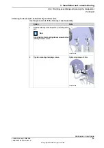
Overview of the assembly order
The IRB 365 is delivered in sub-assemblies which are assembled in the following
order:
Illustration
Assembly order
xx2100000836
Install the base unit.
1
Move the upper arms into
calibration position (horizont-
al).
2
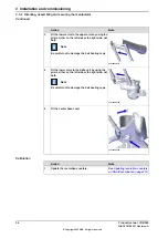
Attach the upper end of the
telescopic shafts to the motor
axes (axes 4 and 5).
3
Attach the lower arms to the
upper arms.
4
Attach the lower arms to the
delta unit.
5
Note
Make sure not to over extend
the length of telescope shafts
due to slide bearing damage
6
Detailed procedures for each step are given further on in this section.
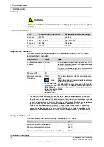
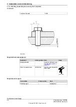
Attachment screws
The table below specifies the type of securing screws and washers to be used for
securing the robot to the base foundation.
M16. Minimum length of thread engage-
ment: 25 mm
Suitable screws
3 pcs
Quantity
Screw class 8.8 with Yield Strength 640
MPa
Quality
17x25x3 coated stainless steel
Suitable washer
3HAC060866-005
200 Nm
Tightening torque
0.3 mm
Level surface requirements
Continues on next page
Product manual - IRB 365
49
3HAC079185-001 Revision: A
© Copyright 2022 ABB. All rights reserved.
3 Installation and commissioning
3.3.4 Orienting, assembling and securing the manipulator
Summary of Contents for IRB 365
Page 1: ...ROBOTICS Product manual IRB 365 ...
Page 8: ...This page is intentionally left blank ...
Page 14: ...This page is intentionally left blank ...
Page 198: ...This page is intentionally left blank ...
Page 216: ...This page is intentionally left blank ...
Page 232: ...This page is intentionally left blank ...
Page 234: ...This page is intentionally left blank ...
Page 238: ......
Page 239: ......


