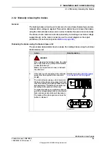


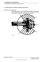
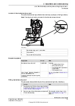
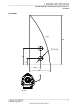
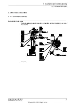
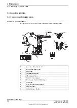

Location of the mechanical stop, axis 1
The extra mechanical stop is fitted to the robot base as shown in the figure below.
Note!
The stop must only be mounted in the direction shown below!
xx0200000205
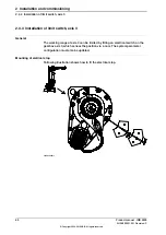
Mechanical stop, axis 1, removable
1
Plain washer
2
Hex socket head cap screw
3
Required equipment
Note
Art. no.
Equipment
Includes:
•
removable stop (2 pcs)
•
plain washers (4 pcs)
•
hex socket head cap screw (4
pcs, M12x30)
•
drill template (1 pc)
3HAB7298-1
Mechanical stop unit, axis 1
Art. no. is specified in
.
-
User’s guide - S4Cplus (BaseWare
OS 4.0)
(RobotWare 4.0)
Technical reference manual - System
parameters
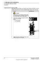
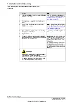
Fitting, mechanical stop axis 1
The procedure below details how to fit a mechanical stop to the robot base.
Note
Action
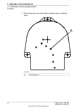
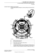
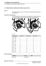
Decide where to fit the extra mechanical stops,
according to the figure
holes for extra stops on page 75
1
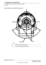
The template is also shown in the
figure
in
scale 1:1.
Make a copy of the drill template, enclosed with
the mechanical stop.
2
Continues on next page
Product manual - IRB 2400
73
3HAC022031-001 Revision: P
© Copyright 2004-2018 ABB. All rights reserved.
2 Installation and commissioning
2.4.2 Mechanically restricting the working range of axis 1
Continued
Summary of Contents for IRB 2400 Series
Page 1: ...ROBOTICS Product manual IRB 2400 ...
Page 8: ...This page is intentionally left blank ...
Page 18: ...This page is intentionally left blank ...
Page 204: ...This page is intentionally left blank ...
Page 220: ...This page is intentionally left blank ...
Page 232: ...This page is intentionally left blank ...
Page 234: ...This page is intentionally left blank ...
Page 240: ......
Page 241: ......


