


4.3 Complete robot
4.3.1 Replacement of cable unit, axes 1-3
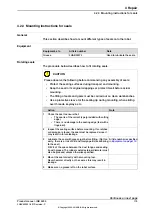
Location of cabling
The cable unit of axes 1-3 is run from the base of the robot to the motors, axes 1,
2 and 3, as shown in the figure below.
A more detailed view of the component and its position may be found in chapter
Spare parts and exploded views
.
xx0500002541
Connectors behind the cover plate at the robot base; R1.MP1-3 and R2.BU1-3.
At the serial measurement board; R2.G (battery), R2.FB1-3.
A
Connectors at motor 2; R3.MP2 and R3.FB2
B
Connectors at motor 3; R3.MP3, R3.FB3,R3.LS1 and R3.LS2
C
Connectors at motor 1; R3.MP1, R3.FB1
D
Upper bracket
E
Cable guide in the middle of the frame
F
Continues on next page
120
Product manual - IRB 2400
3HAC022031-001 Revision: P
© Copyright 2004-2018 ABB. All rights reserved.
4 Repair
4.3.1 Replacement of cable unit, axes 1-3
Summary of Contents for IRB 2400 Series
Page 1: ...ROBOTICS Product manual IRB 2400 ...
Page 8: ...This page is intentionally left blank ...
Page 18: ...This page is intentionally left blank ...
Page 204: ...This page is intentionally left blank ...
Page 220: ...This page is intentionally left blank ...
Page 232: ...This page is intentionally left blank ...
Page 234: ...This page is intentionally left blank ...
Page 240: ......
Page 241: ......


