4 Repair
4.7.5. Replacement of motors, axes 4-6, IRB 2400/10/16
3HAC022031-001 Revision: C
144
©
Co
py
rig
h
t 200
4-
200
8 ABB. All righ
ts reser
v
ed.
4.7.5. Replacement of motors, axes 4-6, IRB 2400/10/16
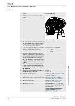
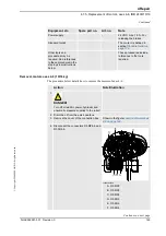
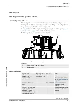
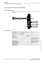
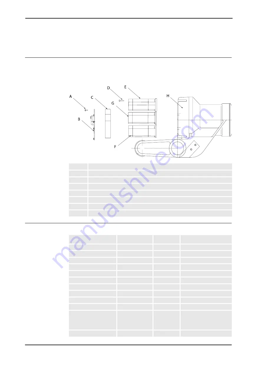
Location of motors axis 4-6
The motors axis 4-6 are located on the back of the upper arm as shown in the figure below:
A more detailed view of the component and its position may be found in chapter
Foldouts
in
the
Product manual, reference information
.
xx0300000108
Required equipment
Note!
The different motors are not compatible. Make sure to replace with correct model!
A
Torx screw
B
Cover
C
Connection box
D
Screw
E
Motor axis 6
F
Motor axis 5
G
Motor axis 4
H
Gearbox
Equipment, etc.
Spare part no.
Art. no.
Note
Motor unit axis 4
3HAC10602-1
(Elmo)
Motor unit axis 4
3HAC021353-001
(Yaskawa)
Motor unit axis 5
3HAC10600-1
IRB 2400/10 (Elmo)
Motor unit axis 5
3HAC10601-1
IRB 2400/16 (Elmo)
Motor unit axis 5
3HAC021722-001
IRB 2400/10/16 (Yaskawa)
Motor unit axis 6
3HAC10602-2
(Elmo)
Motor unit axis 6
3HAC021731-001
(Yaskawa)
O-ring
3HAB3772-12
One piece for each motor.
Locking liquid
3HAB 7116-1 Loctite 243
Bearing grease
3HAB 3537-1
Lubricating oil
3HAC 0860-1 1,500 ml
Optimol BM 100
For the gearbox of axis 4.
Measuring tool
3HAB7887-1
Continues on next page
Summary of Contents for IRB 2400/L
Page 1: ...Product manual Articulated robot IRB 2400 L IRB 2400 10 IRB 2400 16 M2000 M2000A M2004 ...
Page 2: ......
Page 8: ...Table of Contents 6 3HAC022031 001 Revision C Copyright 2004 2008 ABB All rights reserved ...
Page 191: ......
Page 192: ......
Page 193: ......
Page 194: ......
Page 195: ......
Page 198: ......
Page 199: ......
Page 202: ......
Page 203: ......
Page 205: ......
Page 226: ......


