


2 Installation and commissioning
2.4.4. Installation of limit switch, axis 3
59
3HAC022031-001 Revision: C
©
Co
py
rig
h
t 200
4-
200
8 ABB. All righ
ts reser
v
ed.
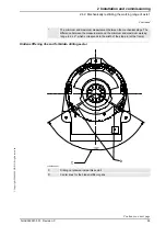
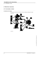
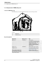
2.4.4. Installation of limit switch, axis 3
General
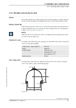
The working range of axis 3 can be limited by fitting an electrical switch on the gearbox axis
3, which senses the position via a cam.
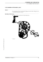
Mounting of eletrical stop
Following illustration shows howe to fit the electrical stop.
xx0200000211
Summary of Contents for IRB 2400/10
Page 1: ...Product manual Articulated robot IRB 2400 L IRB 2400 10 IRB 2400 16 M2000 M2000A M2004 ...
Page 2: ......
Page 8: ...Table of Contents 6 3HAC022031 001 Revision C Copyright 2004 2008 ABB All rights reserved ...
Page 191: ......
Page 192: ......
Page 193: ......
Page 194: ......
Page 195: ......
Page 198: ......
Page 199: ......
Page 202: ......
Page 203: ......
Page 205: ......
Page 226: ......


