


Note
Action
Art. no. is specified in section
.
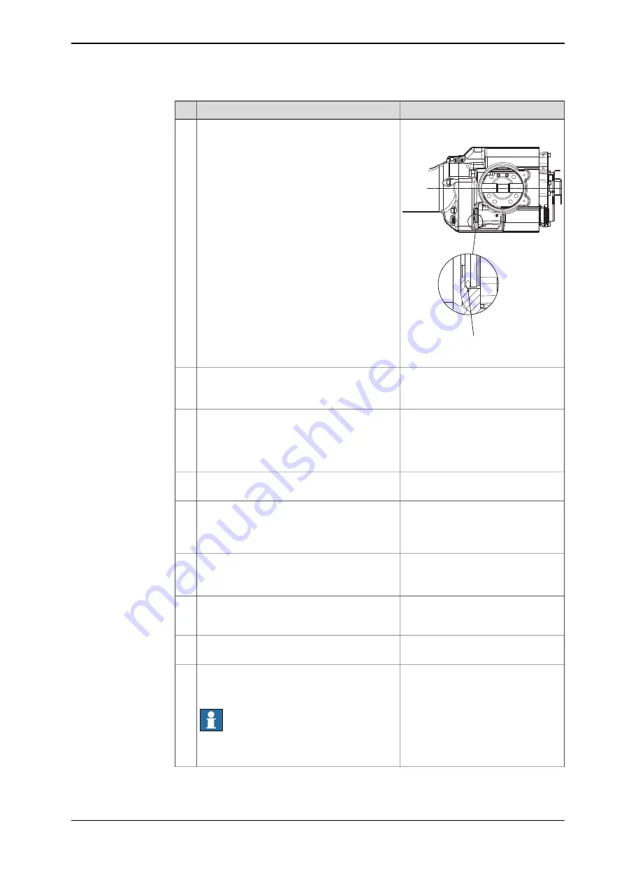
A
xx1200000823
Lightly lubricate a new
o-ring
(A) and put it in
the bottom of the machined hole of the arm
housing.
3
Connect to connector R3.MP4
•
+: pin 7
•
-: pin 8
In order to release the brakes, connect the 24
VDC power supply to the motor.
4
Shown in the figure
Fit the motor with the attachment screws,
compressing the o-ring in axial direction.
Until the motor shaft is adjusted to the gear, as
described in following steps, only tighten the
screws lightly.
5
Tightening torque: approx. 2 Nm.
Art. no. is specified in section
.
Fit the
rotational tool
to the end of the motor
shaft.
6
There should be a barely noticable
gear play.
Adjust the motor in relation to the gear in the
gearbox.
7
Use the arm tool to wiggle the motor shaft back
and forth to feel the play.
Shown in the figure
Tighten the motor
attachment screws
.
8
Tightening torque: 6 Nm ± 0.6 Nm.
Detailed in section
motor and timing belt, axes 5 or 6 on
page 197
.
Refit motors 5 and 6.
9
Detailed in section
Perform a leak-down test.
10
Seal and paint the joints that have been
opened. See
Cut the paint or surface on the
robot before replacing parts on page 118
Note
After all repair work, wipe the robot free from
particles with spirit on a lint free cloth.
11
Continues on next page
Product manual - IRB 140
195
3HAC027400-001 Revision: V
© Copyright 2004-2018 ABB. All rights reserved.
4 Repair
4.7.4 Replacement of motor, axis 4, IRB 1600
Continued
Summary of Contents for IRB 140
Page 1: ...ROBOTICS Product manual IRB 140 ...
Page 8: ...This page is intentionally left blank ...
Page 46: ...This page is intentionally left blank ...
Page 214: ...This page is intentionally left blank ...
Page 228: ...This page is intentionally left blank ...
Page 230: ...This page is intentionally left blank ...
Page 244: ...This page is intentionally left blank ...
Page 250: ......
Page 251: ......


