background image

4.4.4 Inspecting mechanical stops

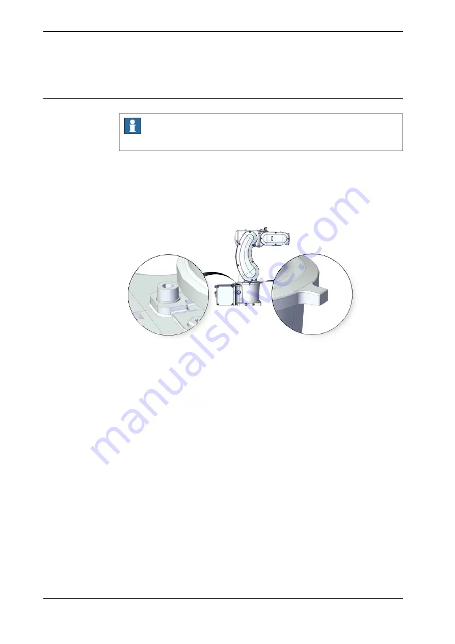
Location of mechanical stops

Note

Only axis-1 and axis-3 are visible for inspection and available for replacement.

Axis 1

xx2200000198

Continues on next page

92

Product manual - IRB 1010

3HAC081964-001 Revision: B

© Copyright 2022 ABB. All rights reserved.

4 Maintenance

4.4.4 Inspecting mechanical stops

Summary of Contents for IRB 1010

Page 1: ...ROBOTICS Product manual IRB 1010 ...

Page 2: ...Trace back information Workspace 22D version a9 Checked in 2022 12 16 Skribenta version 5 5 019 ...

Page 3: ...Product manual IRB 1010 1 5 0 370 OmniCore Document ID 3HAC081964 001 Revision B Copyright 2022 ABB All rights reserved Specifications subject to change without notice ...

Page 4: ...ranty by ABB for losses damage to persons or property fitness for a specific purpose or the like In no event shall ABB be liable for incidental or consequential damages arising from use of this manual and products described herein This manual and parts thereof must not be reproduced or copied without ABB s written permission Keep for future reference Additional copies of this manual may be obtaine...

Page 5: ...on to installation and commissioning 48 3 2 Unpacking 48 3 2 1 Pre installation procedure 49 3 2 2 Risk of tipping stability 50 3 3 On site installation 50 3 3 1 Lifting the robot 50 3 3 1 1 Lifting the robot by one person 52 3 3 1 2 Lifting and rotating a suspended mounted robot 53 3 3 2 Orienting and securing the robot 55 3 3 3 Manually releasing the brakes 57 3 3 4 Setting the system parameters...

Page 6: ...5 1 Replacing the axis 2 drive unit 254 5 5 2 Replacing the axis 3 motor 263 5 5 3 Replacing the axis 5 motor 279 6 Calibration 279 6 1 Introduction to calibration 279 6 1 1 Introduction and calibration terminology 280 6 1 2 Calibration methods 282 6 1 3 When to calibrate 283 6 2 Synchronization marks and axis movement directions 283 6 2 1 Synchronization marks and synchronization position for axe...

Page 7: ...Reference information 317 9 1 Introduction 318 9 2 Applicable standards 319 9 3 Unit conversion 320 9 4 Screw joints 323 9 5 Weight specifications 324 9 6 Standard toolkit 325 9 7 Special tools 327 10 Spare parts 327 10 1 Spare part lists and illustrations 329 Index Product manual IRB 1010 7 3HAC081964 001 Revision B Copyright 2022 ABB All rights reserved Table of contents ...

Page 8: ...This page is intentionally left blank ...

Page 9: ...cation It is the responsibility of the integrator to provide safety and user guides for the robot system Who should read this manual This manual is intended for installation personnel maintenance personnel repair personnel Prerequisites A maintenance repair installation craftsman working with an ABB robot must be trained by ABB and have the required knowledge of mechanical and electrical installat...

Page 10: ...7 3HAC042927 001 Technical reference manual Lubrication in gearboxes 3HAC065041 001 Technical reference manual System parameters i This manual contains all safety instructions from the product manuals for the manipulators and the controllers Revisions Description Revision First edition A Published in release 22D The following updates are done in this revision B Added information about Wrist Optimi...

Page 11: ...ation Troubleshooting Decommissioning Reference information safety standards unit conversions screw joints lists of tools Spare parts list with corresponding figures or references to separate spare parts lists References to circuit diagrams Technical reference manuals The technical reference manuals describe reference information for robotics products for example lubrication the RAPID language and...

Page 12: ...handling of the products The manuals are aimed at those having first hand operational contact with the product that is production cell operators programmers and troubleshooters 12 Product manual IRB 1010 3HAC081964 001 Revision B Copyright 2022 ABB All rights reserved Product documentation Continued ...

Page 13: ...so include specific safety information when dangerous steps are to be performed Read more in the chapter Safety on page 15 Illustrations The product is illustrated with general figures that does not take painting or protection type in consideration Likewise certain work methods or general information that is valid for several product models can be illustrated with illustrations that show a differe...

Page 14: ...This page is intentionally left blank ...

Page 15: ...peration of the robot when the safety devices are defective not in their intended location or in any other way not working When instructions for operation and maintenance are not followed Non authorized design modifications of the robot Repairs on the robot and its spare parts carried out by in experienced or non qualified personnel Foreign objects Force majeure Spare parts and equipment ABB suppl...

Page 16: ...fluence of alcohol drugs or any other intoxicating substances are not allowed to install maintain service repair or use the robot The plant liable must make sure that the personnel is trained on the robot and on responding to emergency or abnormal situations Personal protective equipment Use personal protective equipment as stated in the instructions 16 Product manual IRB 1010 3HAC081964 001 Revis...

Page 17: ...ided will result in ser ious injury DANGER Signal word used to indicate a potentially hazardous situation which if not avoided could result in serious injury WARNING Signal word used to indicate a potentially hazardous situation related to electrical hazards which if not avoided could result in serious injury ELECTRICAL SHOCK Signal word used to indicate a potentially hazardous situation which if ...

Page 18: ...used to indicate where to find additional information or how to do an operation in an easier way TIP 18 Product manual IRB 1010 3HAC081964 001 Revision B Copyright 2022 ABB All rights reserved 1 Safety 1 2 1 Safety signals in the manual Continued ...

Page 19: ...scription Symbol Warning xx0900000812 Warns that an accident may occur if the instructions are not followed that can lead to serious injury possibly fatal and or great damage to the product It applies to warnings that apply to danger with for example contact with high voltage electrical units explosion or fire risk risk of poisonous gases risk of crushing impact fall from height etc Caution xx0900...

Page 20: ...000815 Disassembling this part can cause injury Extended rotation xx0900000814 This axis has extended rotation working area compared to standard Brake release xx0900000808 Pressing this button will release the brakes This means that the robot arm can fall down Continues on next page 20 Product manual IRB 1010 3HAC081964 001 Revision B Copyright 2022 ABB All rights reserved 1 Safety 1 2 2 Safety sy...

Page 21: ...ip over if the bolts are not securely fastened xx1500002402 Crush xx0900000817 Risk of crush injuries Continues on next page Product manual IRB 1010 21 3HAC081964 001 Revision B Copyright 2022 ABB All rights reserved 1 Safety 1 2 2 Safety symbols on manipulator labels Continued ...

Page 22: ...1 1 06 xx1300001087 Moving robot 1 2 3 4 5 6 xx0900000819 The robot can move unexpectedly xx1000001141 1 2 3 4 xx1500002616 Continues on next page 22 Product manual IRB 1010 3HAC081964 001 Revision B Copyright 2022 ABB All rights reserved 1 Safety 1 2 2 Safety symbols on manipulator labels Continued ...

Page 23: ...0001242 Lifting of robot xx0900000822 Oil xx0900000823 Can be used in combination with prohibition if oil is not allowed Mechanical stop xx0900000824 Continues on next page Product manual IRB 1010 23 3HAC081964 001 Revision B Copyright 2022 ABB All rights reserved 1 Safety 1 2 2 Safety symbols on manipulator labels Continued ...

Page 24: ...that this part is pressurized Usually contains additional text with the pressure level Shut off with handle xx0900000827 Use the power switch on the controller Do not step xx1400002648 Warns that stepping on these parts can cause damage to the parts 24 Product manual IRB 1010 3HAC081964 001 Revision B Copyright 2022 ABB All rights reserved 1 Safety 1 2 2 Safety symbols on manipulator labels Contin...

Page 25: ...otective stops and emergency stops are described in the product manual for the controller For more information see Product manual OmniCore E10 Product manual IRB 1010 25 3HAC081964 001 Revision B Copyright 2022 ABB All rights reserved 1 Safety 1 3 Robot stopping functions ...

Page 26: ...le impact caused by a breaking or malfunctioning rotating tool or other device fitted to the robot The maximum TCP speed and the maximum velocity of the robot axes are detailed in the section Robot motion in the product specification for the respective manipulator Consider exposure to hazards such as slipping tripping and falling Hazards due to the working position and posture for a person working...

Page 27: ...obot with external devices to a robot system The integrator of the robot system must ensure that emergency stop functions are interlocked in accordance with applicable standards The integrator of the robot system must ensure that safety functions are interlocked in accordance with applicable standards Other hazards A robot may perform unexpected limited movement WARNING Manipulator movements can c...

Page 28: ...ment of robot arm WARNING Hazards due to the use of brake release devices and or gravity beneath the manipulator shall be considered A robot may perform unexpected limited movement WARNING Manipulator movements can cause serious injuries on users and may damage equipment 28 Product manual IRB 1010 3HAC081964 001 Revision B Copyright 2022 ABB All rights reserved 1 Safety 1 5 Safety during operation...

Page 29: ...ns are working as intended Hot surfaces Surfaces can be hot after running the robot and touching these may result in burns Allow the surfaces to cool down before maintenance or repair Allergic reaction Elimination Action Description Warning Make sure that protective gear like goggles and gloves are al ways worn When working with lubricants there is a risk of an allergic reac tion Allergic reaction...

Page 30: ...iously been drained from the gearbox Specified amount de pends on drained volume Hazards related to batteries Under rated conditions the electrode materials and liquid electrolyte in the batteries are sealed and not exposed to the outside There is a hazard in case of abuse mechanical thermal electrical which leads to the activation of safety valves and or the rupture of the battery container As a ...

Page 31: ...rious injuries on users and may damage equipment Related information See also the safety information related to installation and operation Product manual IRB 1010 31 3HAC081964 001 Revision B Copyright 2022 ABB All rights reserved 1 Safety 1 6 1 Safety during maintenance and repair Continued ...

Page 32: ...quire using an overhead crane or similar equipment Increased injury Before releasing the brakes make sure that the weight of the manipulator does not result in additional hazards for example even more severe injuries on a trapped person DANGER When releasing the holding brakes the robot axes may move very quickly and sometimes in unexpected ways Make sure no personnel is near or beneath the robot ...

Page 33: ... 2 Switch the motor to the MOTORS OFF 3 Inspect and verify that the axis maintains its position If the manipulator does not change position as the motors are switched off then the brake function is adequate Note It is recommended to run the service routine BrakeCheck as part of the regular maintenance see the operating manual for the robot controller For robots with the option SafeMove the Cyclic ...

Page 34: ...ld engineers A risk assessment must be done to address both robot and robot system specific hazards WARNING Hazards due to the use of brake release devices and or gravity beneath the manipulator shall be considered A robot may perform unexpected limited movement WARNING Manipulator movements can cause serious injuries on users and may damage equipment Related information See also the safety inform...

Page 35: ...ment of robot arm WARNING Hazards due to the use of brake release devices and or gravity beneath the manipulator shall be considered A robot may perform unexpected limited movement WARNING Manipulator movements can cause serious injuries on users and may damage equipment Product manual IRB 1010 35 3HAC081964 001 Revision B Copyright 2022 ABB All rights reserved 1 Safety 1 8 Safety during decommiss...

Page 36: ...This page is intentionally left blank ...

Page 37: ...re that is especially adapted for flexible use and can communicate extensively with external systems Benefit from its smaller size and lighter weight the IRB 1010 is easy for deployment and suitable for manufacturing processes in limited spaces e g film peeling The robot is equipped with the OmniCore E10 controller and robot control software RobotWare 7 Product manual IRB 1010 37 3HAC081964 001 Re...

Page 38: ...ctions of the robots stress forces The directions are valid for all floor mounted table mounted wall mounted and suspended robots xy xy z z T F F T xx1100000521 Force in any direction in the XY plane Fxy Force in the Z plane Fz Bending torque in any direction in the XY plane Txy Bending torque in the Z plane Tz Continues on next page 38 Product manual IRB 1010 3HAC081964 001 Revision B Copyright 2...

Page 39: ...Force z 121 Nm 70 Nm Torque xy 51 Nm 30 Nm Torque z Requirements foundation The table shows the requirements for the foundation where the weight of the installed robot is included Note Value Requirement Flat foundations give better repeatability of the resolver calibration compared to original settings on delivery from ABB 0 1 500 mm Flatness of foundation surface The value for levelness aims at t...

Page 40: ...s in this region will be amplified although somewhat damped by the servo control This might be a problem depending on the requirements from the applications If this is a problem the robot needs to be isolated from the environment Storage conditions robot The table shows the allowed storage conditions for the robot Value Parameter 25 C 13 F Minimum ambient temperature 55 C 131 F Maximum ambient tem...

Page 41: ...tal information The product complies with IEC 63000 Technical documentation for the assessment of electrical and electronic products with respect to the restriction of hazardous substances Product manual IRB 1010 41 3HAC081964 001 Revision B Copyright 2022 ABB All rights reserved 2 Manipulator description 2 2 Technical data Continued ...

Page 42: ...8 B 185 185 375 A 135 110 110 132 C 119 184 xx2200000188 Description Pos Turning radius R67 A Turning radius R83 B Turning radius R113 C 42 Product manual IRB 1010 3HAC081964 001 Revision B Copyright 2022 ABB All rights reserved 2 Manipulator description 2 3 Dimensions ...

Page 43: ...le of axes 2 and 3 Angle degrees Positions at wrist center mm Position in the figure axis 3 axis 2 Z X 0 0 375 185 pos0 90 0 560 0 pos1 50 0 233 3 118 9 pos2 90 90 190 370 pos3 90 125 22 2 303 1 pos4 180 125 225 6 270 5 pos5 180 75 59 2 226 6 pos6 50 75 316 1 11 0 pos7 90 75 285 8 357 4 pos8 Continues on next page Product manual IRB 1010 43 3HAC081964 001 Revision B Copyright 2022 ABB All rights r...

Page 44: ...is 3 170 Axis 4 125 Axis 5 Default value 360 Axis 6 Maximum revolution value 242 The default working range for axis 6 can be extended by changing parameter values in the soft ware 44 Product manual IRB 1010 3HAC081964 001 Revision B Copyright 2022 ABB All rights reserved 2 Manipulator description 2 4 Working range Continued ...

Page 45: ...estroy sensitive electronics Safe handling Use one of the following alternatives Use a wrist strap Wrist straps must be tested frequently to ensure that they are not damaged and are operating correctly Use an ESD protective floor mat The mat must be grounded through a current limiting resistor Use a dissipative table mat The mat should provide a controlled discharge of static voltages and must be ...

Page 46: ...This page is intentionally left blank ...

Page 47: ...commenced all safety information must be observed There are general safety aspects that must be read through as well as more specific safety information that describes the danger and safety risks when performing the procedures Read the chapter Safety on page15 before performing any installation work Note Always connect the IRB 1010 and the robot to protective earth and residual current device RCD ...

Page 48: ... lifting accessory used if required is suitable to handle the weight of the robot as specified in Weight robot on page 38 5 If the robot is not installed directly it must be stored as described in Storage condi tions robot on page 40 6 Make sure that the expected operating environment of the robot conforms to the specifications as described in Operating conditions robot on page 40 7 Before taking ...

Page 49: ...n is the most stable position Do not change the robot position before securing it to the foundation Shipping and transportation position This figure shows the robot in its shipping position and transportation position xx2200000181 WARNING The robot is likely to be mechanically unstable if not secured to the foundation Product manual IRB 1010 49 3HAC081964 001 Revision B Copyright 2022 ABB All righ...

Page 50: ...the arm The following figure illustrates the recommended grasping location of the robot xx2200000196 Lifting and transporting the robot Action CAUTION The IRB 1010 weighs 13 5 kg and can be lifted by one person 1 Grasp the robot as instructed in Grasping location on page 50 2 Lift the robot 3 Continues on next page 50 Product manual IRB 1010 3HAC081964 001 Revision B Copyright 2022 ABB All rights ...

Page 51: ...ng and transporting It could damage the robot 4 Secure the robot on a workbench according to section Orienting and securing the robot on page 53 5 Product manual IRB 1010 51 3HAC081964 001 Revision B Copyright 2022 ABB All rights reserved 3 Installation and commissioning 3 3 1 1 Lifting the robot by one person Continued ...

Page 52: ... How to lift and turn the robot to a suspended position Contact ABB for more information 52 Product manual IRB 1010 3HAC081964 001 Revision B Copyright 2022 ABB All rights reserved 3 Installation and commissioning 3 3 1 2 Lifting and rotating a suspended mounted robot ...

Page 53: ... configuration of the base is shown in the figure in Hole con figuration base on page 54 Prepare the installation site with attachment holes The foundation surface must be clean and un painted 2 3 CAUTION When the robot is put down after being lifted or transported there is a risk of it tipping if not properly secured 4 See Lifting the robot on page 50 Lift the robot 5 2 pcs D6x20 ISO 2338 6m6x20 ...

Page 54: ...t 7 110 110 2 6 H7 0 012 0 8 6 H 8 0 0 1 8 0 8 135 9 9 4 4 132 J J 4 x 1 4 3 4 x 9 4 x 1 8 4 x 1 6 7 SECTION J J xx2200000191 54 Product manual IRB 1010 3HAC081964 001 Revision B Copyright 2022 ABB All rights reserved 3 Installation and commissioning 3 3 2 Orienting and securing the robot Continued ...

Page 55: ...ipped with a brake release unit Note Action Note If the robot is not connected to the controller power must be supplied to the connector R1 MP according to the section Supplying power to connector R1 MP on page 56 1 DANGER When releasing the holding brakes the robot axes may move very quickly and sometimes in unexpec ted ways Make sure no personnel is near or beneath the ro bot 2 Continues on next...

Page 56: ...er to enable the brake release buttons Note Action DANGER Incorrect connections such as supplying power to the wrong pin may cause all brakes to be released simultaneously and instantly 1 xx1800002443 Supply 0V on pin 12 24V on pin 11 Note Do not interchange the 24V and 0V pins If they are mixed up damage can be caused to internal electrical components 2 Use the brake releasing button as described...

Page 57: ...tem parameters Note The mounting angle must be configured correctly in the system parameters so that the robot system can control the movements in the best possible way An incorrect definition of the mounting angle will result in Overloading the mechanical structure Lower path performance and path accuracy Some functions will not work properly for example Load Identification and Collision detectio...

Page 58: ...rameters Gamma Rotation Gamma Rotation defines the orientation of the robot foot on the travel carriage track motion Mounting angles and values The parameter Gravity Beta or Gravity Alpha specifies the mounting angle of the robot in radians It is calculated in the following way Gravity Beta A x 3 141593 180 B radians where A is the mounting angle in degrees and B is the mounting angle in radians G...

Page 59: ... Note For suspended robots 180 it is recommended to use Gravity Beta instead of Gravity Alpha Defining the system parameters in RobotWare The value of the system parameters that define the mounting angle must be redefined when changing the mounting angle of the robot The parameters belong to the type Robot in the topic Motion Continues on next page Product manual IRB 1010 59 3HAC081964 001 Revisio...

Page 60: ...ers The system parameters are configured in RobotStudio or on the FlexPendant 60 Product manual IRB 1010 3HAC081964 001 Revision B Copyright 2022 ABB All rights reserved 3 Installation and commissioning 3 3 4 Setting the system parameters for an inverted or a tilted robot Continued ...

Page 61: ...tops or major damage to the robot Load diagrams permitted extra loads equipment and their positions are specified in the product specification The loads must be defined in the software Stopping time and braking distances The performance of the motor brake depends on if there are any loads attached to the robot See Product specification Robot stopping distances according to ISO 10218 1 Product manu...

Page 62: ...ning radius R83 B Turning radius R113 C Attachment holes and dimensions Extra loads can be mounted on robot Definitions of dimensions and masses are shown in the following figures The robot is supplied with holes for fitting extra equipment Continues on next page 62 Product manual IRB 1010 3HAC081964 001 Revision B Copyright 2022 ABB All rights reserved 3 Installation and commissioning 3 3 6 Fitti...

Page 63: ...AIL A 18 2x M3x4 5 DETAIL B 135 184 119 18 4x M3x5 5 DETAIL D xx2200000189 Tool flange standard G 31 5 5 H7 0 012 0 7 4xM5 8 Drill dp 9 5 4x 90 4 5 I I DETAIL G 0 05 0 2 20 H7 0 021 0 9 5 I I xx2200000190 Continues on next page Product manual IRB 1010 63 3HAC081964 001 Revision B Copyright 2022 ABB All rights reserved 3 Installation and commissioning 3 3 6 Fitting equipment on the robot robot dime...

Page 64: ...he synchronization mark see Synchronization marks and synchronization position for axes on page 283 Fastener quality When fitting tools on the tool flange only use screws with quality 12 9 For other equipment use suitable screws and tightening torque for your application 64 Product manual IRB 1010 3HAC081964 001 Revision B Copyright 2022 ABB All rights reserved 3 Installation and commissioning 3 3...

Page 65: ...rs On State 3 The lamp is now ready for use and is lit in MOTORS ON mode 4 Installation of signal lamp from MON_LAMP signal Action DANGER Make sure that all supplies for electrical power hydraulic pressure and air pressure are turned off 1 For robots with OmniCore E line 2 Connect the lamp cable connector to the MON connector on the controller Note The MON connector provides MON_LAMP output signal...

Page 66: ... system may be found in Technical reference manual System parameters 66 Product manual IRB 1010 3HAC081964 001 Revision B Copyright 2022 ABB All rights reserved 3 Installation and commissioning 3 3 7 Installation of signal lamp option Continued ...

Page 67: ...Note The mechanical stops are only installed as safety precaution to physically stop the robot from exceeding the working range set A collision with a mechanical stop always requires actions for repair and troubleshooting Movable mechanical stopii Fixed mechanical stopi Axis yes The working range can be reduced by altering the parameter values In stallation of additional mechanical stops is recomm...

Page 68: ...eration of robot Axis 2 axis 4 and axis 5 have castings as mechanical stops to restrict working range which could not be replaced Axis 1 xx2200000198 Continues on next page 68 Product manual IRB 1010 3HAC081964 001 Revision B Copyright 2022 ABB All rights reserved 3 Installation and commissioning 3 4 2 Mechanically restricting the working range ...

Page 69: ...is 3 xx2200000200 Continues on next page Product manual IRB 1010 69 3HAC081964 001 Revision B Copyright 2022 ABB All rights reserved 3 Installation and commissioning 3 4 2 Mechanically restricting the working range Continued ...

Page 70: ...is 5 xx2200000202 Continues on next page 70 Product manual IRB 1010 3HAC081964 001 Revision B Copyright 2022 ABB All rights reserved 3 Installation and commissioning 3 4 2 Mechanically restricting the working range Continued ...

Page 71: ... Mechanical stop washer Required tools and equipment Note Article number Equipment Content is defined in section Standard toolkit on page 324 Standard toolkit Replacing the axis 1 and axis 3 mechanical stops Note Action Jog the robot to a position where the mechanical stops are most easily accessed 1 DANGER Turn off all electric power supply hydraulic pressure supply air pressure supply to the rob...

Page 72: ...chanical stop screw 9ADA186 23 Mechanical stop washer 9ADA762 6 Axis 3 Mechanical stop screw 9ADA186 23 Tightening torque 5 Nm Secure the mechanical stops 5 72 Product manual IRB 1010 3HAC081964 001 Revision B Copyright 2022 ABB All rights reserved 3 Installation and commissioning 3 4 2 Mechanically restricting the working range Continued ...

Page 73: ...measure Additional mechanical stops shall be designed according to actual application and site requirements Refer to the following hole dimension on swing bottom to prepare the stops PCD 130 1 0 x 3 0 3 0 11xM3 5 5 xx2200001082 Note Additional mechanical stops are not delivered with the robot Contact ABB for more information Product manual IRB 1010 73 3HAC081964 001 Revision B Copyright 2022 ABB A...

Page 74: ...nt fitted on the robot by the customer low voltage signals and high voltage power supply protective ground Customer cables The customer cables also handle databus communication The customer cables also include the air hose See the product manual for the controller see document number in References on page 10 The hose for compressed air is integrated with the manipu lator cable harness Air hoses Ro...

Page 75: ...HAC067446 002 Signal cable shielded 7 m 3HAC067446 003 Signal cable shielded 15 m Bending radius for static floor cables The minimum bending radius is 10 times the cable diameter for static floor cables A B xx1600002016 Diameter A Diameter x10 B Continues on next page Product manual IRB 1010 75 3HAC081964 001 Revision B Copyright 2022 ABB All rights reserved 3 Installation and commissioning 3 5 1 ...

Page 76: ...izing between control cabinet manipulator and any peripheral devices xx2200000001 Customer cables CP CS cable Article number CP CS cable length 3HAC067449 001 3 m 3HAC067449 002 7 m 76 Product manual IRB 1010 3HAC081964 001 Revision B Copyright 2022 ABB All rights reserved 3 Installation and commissioning 3 5 1 Robot cabling and connection points Continued ...

Page 77: ...meter of air hose 4 mm 2 Max 5 bar Air A 30 V 1 54 A 12 wires Customer power signal R1 R2 C1 B Connector kits optional Connector kits base R1 C1 connector on the base is part of the CP CS cable For details about the robot cabling see Robot cabling and connection points on page 74 Connector kits wrist The table describes the CP CS connector kits for wrist Art no Description Position 3HAC066098 001 ...

Page 78: ...iring water and dust proofing Always remember to refit the protection covers after removing them A A B C xx2200000195 Air hose connector protection covers A CP CS connector protection covers B SMB connector protection cover C 78 Product manual IRB 1010 3HAC081964 001 Revision B Copyright 2022 ABB All rights reserved 3 Installation and commissioning 3 5 2 Customer connections Continued ...

Page 79: ...be regulated with the RAPID instruction VelSet Start the robot with its normal program but with reduced speed 1 Adjusting the speed and acceleration during warm up Depending on how cold the environment is and what program is being used the speed might need to be ramped up until reached maximum The table shows examples of how to adjust the speed Speed velocity AccSet Work cycles v100 100 mm s 20 20...

Page 80: ...This page is intentionally left blank ...

Page 81: ...any service work There are general safety aspects that must be read through as well as more specific safety information that describes the danger and safety risks when performing the procedures Read the chapter Safety on page 15 before performing any service work The maintenance must be done by qualified personnel in accordance with the safety requirements set forth in the applicable national and ...

Page 82: ...pecified in months regardless of whether the system is running or not Operating time specified in operating hours More frequent running means more frequent maintenance activities Robots with the functionality Service Information System activated can show active counters in the device browser in RobotStudio or on the FlexPendant 82 Product manual IRB 1010 3HAC081964 001 Revision B Copyright 2022 AB...

Page 83: ...n page 92 x Inspecting the mechanical stop Lubricating the cable package on page 95 x iv Lubricating the robot harness Replacing the battery pack on page 97 x v Replacing the SMB battery pack Recommended to robots without the SafeMove option See Operating manual OmniCore x vii Running the Brake Check routinevi x Overhaul of complete robot i Regularly implies that the activity is to be performed re...

Page 84: ...dy included in the application vii Recommended test interval is within the range 8 48 hours 84 Product manual IRB 1010 3HAC081964 001 Revision B Copyright 2022 ABB All rights reserved 4 Maintenance 4 2 2 Maintenance schedule Continued ...

Page 85: ...sage in regard to movement most material handling applications and limited use of bending backwards mode of axis 3 ii Severe chemical or thermal environments or similar environments can result in shortened life expectancy iii Examples of extreme usage in regard to movement press tending very severe palletizing applications major use of axis 1 movement and major use of bending backwards of axis 3 P...

Page 86: ...ore cleaning Do not point the water jet at connectors joints sealings or gaskets Do not use compressed air to clean the robot Do not use solvents that are not approved by ABB to clean the robot Do not spray from a distance closer than 0 4 m Do not remove any covers or other protective devices before cleaning the robot Cleaning methods This following table defines what cleaning methods are allowed ...

Page 87: ...flow Cables Movable cables need to be able to move freely Remove waste material such as sand dust and chips if it prevents cable movement Clean the cables if they have a crusty surface for example from dry release agents Product manual IRB 1010 87 3HAC081964 001 Revision B Copyright 2022 ABB All rights reserved 4 Maintenance 4 3 1 Cleaning the IRB 1010 Continued ...

Page 88: ... inspected The symbols are described in section Safety symbols on manipulator labels on page19 F H UL label G E A B C D Calibration label A A B xx2200000197 ABB logo A Robot model B Continues on next page 88 Product manual IRB 1010 3HAC081964 001 Revision B Copyright 2022 ABB All rights reserved 4 Maintenance 4 4 1 Inspecting the information labels ...

Page 89: ...on DANGER Turn off all electric power supply hydraulic pressure supply air pressure supply to the robot before entering the safeguarded space 1 Inspect the labels located as shown in the figures 2 Article numbers for the labels and plate set is specified in Spare parts on page 327 Replace any missing or damaged labels 3 Product manual IRB 1010 89 3HAC081964 001 Revision B Copyright 2022 ABB All ri...

Page 90: ...n robot cabling Use this procedure to inspect the robot cabling Note Action DANGER Turn off all electric power supply to the robot hydraulic pressure supply to the robot air pressure supply to the robot Before entering the robot working area 1 Visually inspect the control cabling between the robot and control cabinet Look for abrasions cuts or crush damage 2 Replace the cabling if wear or damage i...

Page 91: ...lue decreases 28 when the timing belt has been installed and used for more than 12 hours but less than 150 hours When the timing belt has been installed and used for more than 150 hours both the force and frequency values decrease 30 ii The value range is only for reference Inspecting timing belts Use this procedure to inspect timing belts Information Action DANGER Turn off all electric power supp...

Page 92: ...ote Only axis 1 and axis 3 are visible for inspection and available for replacement Axis 1 xx2200000198 Continues on next page 92 Product manual IRB 1010 3HAC081964 001 Revision B Copyright 2022 ABB All rights reserved 4 Maintenance 4 4 4 Inspecting mechanical stops ...

Page 93: ...3 Mechanical stop screw Used with Mechanical stop screw to mechanically restrict the mo tion of axis 1 9ADA762 6 Mechanical stop washer Required tools and equipment Visual inspection no tools are required Other tools and procedures may be required if the spare part needs to be replaced These are specified in the replacement procedure Continues on next page Product manual IRB 1010 93 3HAC081964 001...

Page 94: ...ring the robot working area 1 See figures in Location of mechanical stops on page 92 Inspect the mechanical stops 2 Replace if the mechanical stop is bent loose damaged Note The expected life of gearboxes can be re duced as a result of collisions with the mechanical stop 3 94 Product manual IRB 1010 3HAC081964 001 Revision B Copyright 2022 ABB All rights reserved 4 Maintenance 4 4 4 Inspecting mec...

Page 95: ...the spare part needs to be replaced These are specified in the replacement procedure Required consumables Note Article number Consumable FM 222 3HAC029132 001 Grease Lubricating the cable package Use this procedure to lubricate the cable package Information Action DANGER Turn off all electric power supply hydraulic pressure supply air pressure supply to the robot before entering the robot working ...

Page 96: ...8 If any damage or wear is detected the part must be replaced 4 Apply grease to the cable package cover all moving area of the package 5 Apply grease to the covers that have con tacting area with the cable package 6 96 Product manual IRB 1010 3HAC081964 001 Revision B Copyright 2022 ABB All rights reserved 4 Maintenance 4 5 1 Lubricating the cable package Continued ...

Page 97: ...yABB Business Portal www abb com myABB Note Article number Spare part Battery includes protection cir cuits Only replace with the spe cified spare part or an ABB ap proved equivalent 3HAC044075 001 Battery pack Required tools and equipment Note Article number Equipment Content is defined in section Standard toolkit on page 324 Standard toolkit Continues on next page Product manual IRB 1010 97 3HAC...

Page 98: ...ery pack Note Action Decide which calibration routine to use and take actions accordingly prior to beginning the repair procedure 1 xx2200000173 Jog the robot to the synchronization position 2 DANGER Turn off all electric power supply hydraulic pressure supply air pressure supply to the robot before entering the safeguarded space 3 Disconnecting the SMB connectors Note Action DANGER Make sure that...

Page 99: ...ved 3 xx2200000013 Disconnect the connectors SMB P7 SMB J1 SMB J2 Tip Take photos of the connector and cable position before disconnecting them to have as a reference when reconnecting 4 Remove the SMB cover completely from the base 5 Removing the battery pack Note Action DANGER Make sure that all supplies for electrical power hydraulic pressure and air pressure are turned off 1 ELECTROSTATIC DISC...

Page 100: ...ry pack Note Action ELECTROSTATIC DISCHARGE ESD The unit is sensitive to ESD Before handling the unit read the safety information in section The unit is sensitive to ESD on page 45 1 xx2200000015 Secure the battery pack using the cable strap 2 Continues on next page 100 Product manual IRB 1010 3HAC081964 001 Revision B Copyright 2022 ABB All rights reserved 4 Maintenance 4 6 1 Replacing the batter...

Page 101: ...mber markings on the connectors for help to find the corresponding connector 2 xx2200000013 Route and secure the cabling with cable straps CAUTION Correct cable routing is highly important If the cables are routed and secured incorrectly the cables can be damaged 3 Screw M3x8 12 9 Lafre 2C2B FC6 9 4 pcs Refit the SMB cover to the base 4 Tightening torque 1 2 Nm xx2200000012 Continues on next page ...

Page 102: ...tion on page 279 Recalibrate the robot 1 DANGER Make sure all safety requirements are met when performing the first test run 2 102 Product manual IRB 1010 3HAC081964 001 Revision B Copyright 2022 ABB All rights reserved 4 Maintenance 4 6 1 Replacing the battery pack Continued ...

Page 103: ...the article number and the revision of both the replaced unit and the replacement unit This is particularly important for safety equipment to maintain the safety integrity of the installation Safety information Make sure to read through the chapter Safety on page 15 before commencing any service work Note If the IRB 1010 is connected to power always make sure that the IRB 1010 is connected to prot...

Page 104: ...s or protect it well before actual mounting The fitting of sealings and gears must be carried out on clean workbenches Use a protective sleeve for the main lip during mounting when sliding over threads keyways or other sharp edges Note Action Check the sealing to ensure that The sealing is of the correct type There is no damage on the main lip 1 Inspect the shaft surface before mounting If scratch...

Page 105: ...f the space between the dust lip and the main lip with grease If the sealing is without dust lip just lubricate the main lip with a thin layer of grease A xx2000000072 A Gap Mount the sealing correctly with a mounting tool Never hammer directly on the sealing as this may result in leakage 4 Continues on next page Product manual IRB 1010 105 3HAC081964 001 Revision B Copyright 2022 ABB All rights r...

Page 106: ...ten the screws evenly when fastening the flange joint 4 O rings The following procedure describes how to fit o rings Note Action Ensure that the correct o ring size is used 1 Defective o rings including damaged or deformed o rings may not be used Check the o ring for surface defects burrs shape accuracy or deformation 2 Check the o ring grooves 3 The grooves must be geometrically correct and shoul...

Page 107: ...mage to the robot Elimination To eliminate the danger after service work has been performed inside the SMB recess follow the procedure below Action Make sure the power is turned off 1 Remove the push button guard if necessary 2 Verify that the push buttons of the brake release unit are working by pressing them down one by one 3 Make sure none of the buttons are jammed in the tube If a button gets ...

Page 108: ...sed for cabling from base bottom as an option The cable package is located as shown in the figures Left view Right view xx2100002837 xx2100002836 Required spare parts Note The spare part numbers that are listed in the table can be out of date See the latest spare parts of the IRB 1010 via myABB Business Portal www abb com myABB Note Article number Spare part 3HAC076884 001 Cable harness basic 3HAC...

Page 109: ...01 Swing top cover 3HAC082446 001 Lower arm cover left 3HAC082447 001 Lower arm cover right 3HAC082445 001 Housing cover 3HAC082443 001 Wrist cover 3HAC082442 001 Tilt cover Used to mechanically restrict the motion of axis 1 and axis 3 9ADA186 23 Mechanical stop screw Used with Mechanical stop screw to mechanically restrict the mo tion of axis 1 9ADA762 6 Mechanical stop washer M3x8 12 9 Lafre 2C2...

Page 110: ...umber Consumable Cable straps FM 222 3HAC029132 001 Grease Harmonic Grease Flexolub 1A Used to lubricate the seals 3HAC038379 001 Grease Cooling pads are wear parts One cooling pad sheet contains 6 pieces of small pad Replace if damaged with one piece each time 3HAC071021 001 Cooling pad for axis 2 motor Deciding calibration routine Decide which calibration routine to be used based on the informat...

Page 111: ...move all external cable packages DressPack and tools from the robot Removing the cable package Use these procedures to remove the cable package Preparations before removing the cable package Note Action Decide which calibration routine to use and take actions accordingly prior to beginning the repair procedure 1 xx2200000175 Jog the robot to the specified position Axis 1 0 Axis 2 0 Axis 3 0 Axis 4...

Page 112: ...ION There is cabling attached to the cover The cover cannot be removed completely until the connect ors are removed 2 xx2200000031 For robots with air hoses Disconnect the air hoses 3 xx2200000032 For robots with CP CS cabling Disconnect the connector R2 C1 Tip Take photos of the connector and cable position before disconnecting them to have as a reference when reconnecting 4 Continues on next pag...

Page 113: ...tions to not get it stuck 2 xx2200000033 Remove the axis 6 cable bracket CAUTION Be aware of the cablings that are attached to the cable bracket The bracket cannot be removed completely until the cablings are removed from the plate 3 xx2200000034 Cut the cable straps 4 Pulling out the cable package from axis 5 Note Action DANGER Make sure that all supplies for electrical power hydraulic pressure a...

Page 114: ...m axis 5 Note Action DANGER Make sure that all supplies for electrical power hydraulic pressure and air pressure are turned off 1 xx2200000038 Remove the axis 5 cable bracket CAUTION Be aware of the cablings that are attached to the cable bracket The bracket cannot be removed completely until the cablings are removed from the plate 2 xx2200000039 Cut the cable strap 3 Continues on next page 114 Pr...

Page 115: ... power hydraulic pressure and air pressure are turned off 1 CAUTION Loosening timing belts will release axes This means the axes can fall down Make sure axes are well supported before loosening timing belts 2 xx2200000042 Loosen the screws and move the motor slightly to slacken the timing belt 3 Continues on next page Product manual IRB 1010 115 3HAC081964 001 Revision B Copyright 2022 ABB All rig...

Page 116: ...This means the axes can fall down Make sure axes are well supported before remov ing motors 2 xx2200000040 Disconnect the connector MP5 Tip Take photos of the connector and cable position before disconnecting them to have as a reference when reconnecting 3 xx2200000044 Remove the screws and washers 4 Continues on next page 116 Product manual IRB 1010 3HAC081964 001 Revision B Copyright 2022 ABB Al...

Page 117: ...ng the wrist unit from the axis 3 4 assembly unit Note Action Connect the power supply to axis 3 motor and release the axis 3 brake to move the axis 3 to 90 Then disconnect the power supply Note The robot is not connected to the controller during replacement power must be supplied to the con nector R1 MP according to the section Supplying power to connector R1 MP on page 56 1 DANGER Make sure that...

Page 118: ...ring replacement power must be supplied to the con nector R1 MP according to the section Supplying power to connector R1 MP on page 56 5 Disconnecting the axis 4 motor connectors Note Action DANGER Make sure that all supplies for electrical power hydraulic pressure and air pressure are turned off 1 xx2200000050 Cut the cable straps 2 Continues on next page 118 Product manual IRB 1010 3HAC081964 00...

Page 119: ... Action DANGER Make sure that all supplies for electrical power hydraulic pressure and air pressure are turned off 1 Wrap the connectors with the masking tape 2 xx2200000052 Remove the axis 4 cable bracket to separate the cable from the housing 3 xx2200000558 Remove the axis 4 cable bracket from the cable 4 Continues on next page Product manual IRB 1010 119 3HAC081964 001 Revision B Copyright 2022...

Page 120: ...sure and air pressure are turned off 1 xx2200000054 Cut the cable straps 2 xx2200000055 Disconnect the connectors FB3 MP3 Tip Take photos of the connector and cable position before disconnecting them to have as a reference when reconnecting 3 Removing the axis 3 timing belt Note Action DANGER Make sure that all supplies for electrical power hydraulic pressure and air pressure are turned off 1 Cont...

Page 121: ...t from its groove on the motor 4 Removing the axis 3 motor Note Action DANGER Make sure that all supplies for electrical power hydraulic pressure and air pressure are turned off 1 CAUTION Removing motors will release axes This means the axes can fall down Make sure axes are well supported before remov ing motors 2 Continues on next page Product manual IRB 1010 121 3HAC081964 001 Revision B Copyrig...

Page 122: ...at all supplies for electrical power hydraulic pressure and air pressure are turned off 1 Wrap the connectors with the masking tape 2 xx2200000060 Remove the axis 3 cable protector 3 xx2200000061 Continues on next page 122 Product manual IRB 1010 3HAC081964 001 Revision B Copyright 2022 ABB All rights reserved 5 Repair 5 3 1 Replacing the cable package Continued ...

Page 123: ... to the con nector R1 MP according to the section Supplying power to connector R1 MP on page 56 1 DANGER Make sure that all supplies for electrical power hydraulic pressure and air pressure are turned off 2 xx2200000540 Remove the swing top cover 3 Removing the axis 2 drive unit Note Action DANGER Make sure that all supplies for electrical power hydraulic pressure and air pressure are turned off 1...

Page 124: ...ent 3 xx2200000063 Remove the axis 2 cable bracket 4 xx2200000065 Remove the outermost screws flange screws 11 pcs securing the axis 2 drive unit to the axis 3 4 assembly unit 5 xx2200000066 Remove the screws 12 pcs securing the axis 2 drive unit to the axis 1 assembly unit CAUTION Do not remove the innermost screws 16 pcs xx2200000068 6 Continues on next page 124 Product manual IRB 1010 3HAC08196...

Page 125: ...nnector is disconnected 8 xx2200000064 Disconnect the connector FB2 Tip Take photos of the connector and cable position before disconnecting them to have as a reference when reconnecting 9 Separating the cable package from axis 2 Note Action DANGER Make sure that all supplies for electrical power hydraulic pressure and air pressure are turned off 1 xx2200000069 Remove the axis 2 cable protector 2 ...

Page 126: ... can result in hazardous failures CAUTION There are cabling attached to the cover The cover cannot be removed completely until the connectors are removed 3 xx2200000013 Disconnect the connectors SMB P7 SMB J1 SMB J2 Tip Take photos of the connector and cable position before disconnecting them to have as a reference when reconnecting 4 Remove the SMB cover completely from the base 5 Removing the ba...

Page 127: ...efore handling the unit read the safety information in section The unit is sensitive to ESD on page 45 2 xx2200000072 Disconnect the earth cable 3 Disconnecting the connectors from the base interface panel Note Action DANGER Make sure that all supplies for electrical power hydraulic pressure and air pressure are turned off 1 ELECTROSTATIC DISCHARGE ESD The unit is sensitive to ESD Before handling ...

Page 128: ... and cable position before disconnecting them to have as a reference when reconnecting 5 xx2200000075 xx2200000076 Remove the main power connector R1 MP 6 Disconnecting the axis 1 motor connectors Note Action DANGER Make sure that all supplies for electrical power hydraulic pressure and air pressure are turned off 1 Continues on next page 128 Product manual IRB 1010 3HAC081964 001 Revision B Copyr...

Page 129: ...os of the connector and cable position before disconnecting them to have as a reference when reconnecting 2 Putting the robot on its side Note Action DANGER Make sure that all supplies for electrical power hydraulic pressure and air pressure are turned off 1 CAUTION The base and axis 1 assembly unit weigh 3 4 kg and can be lifted by one person 2 WARNING The robot is likely to be mechanically unsta...

Page 130: ... 2 xx2200000080 Remove the base Note Pay attention to the axis 1 motor cablings which should be carefully pulled out from the pointed hole first before removing the base xx2200000081 3 Separating the cable package from the axis 1 assembly unit Note Action DANGER Make sure that all supplies for electrical power hydraulic pressure and air pressure are turned off 1 Continues on next page 130 Product ...

Page 131: ... the cable package Note Action DANGER Make sure that all supplies for electrical power hydraulic pressure and air pressure are turned off 1 Wrap the connectors with the masking tape 2 Continues on next page Product manual IRB 1010 131 3HAC081964 001 Revision B Copyright 2022 ABB All rights reserved 5 Repair 5 3 1 Replacing the cable package Continued ...

Page 132: ...200000087 Insert the cable package into the axis 1 assembly unit through the pointed hole CAUTION Note the correct direction of the cable package Make sure that no cables or hoses are twisted or strained Reroute if necessary 2 Cable protector axis 1 3HAC078560 001 Refit the axis 1 cable protector 3 Screw M2 5x6 12 9 Lafre 2C2B FC6 9 3 pcs Tightening torque 0 4 Nm xx2200000084 Continues on next pag...

Page 133: ...rted in the cable protector and then bend back after a half turn CAUTION Make sure that no cables or hoses are twisted or strained Reroute if necessary 4 Front view xx2200000088 Right view xx2200000089 Left view xx2200000559 Back view xx2200000090 Continues on next page Product manual IRB 1010 133 3HAC081964 001 Revision B Copyright 2022 ABB All rights reserved 5 Repair 5 3 1 Replacing the cable p...

Page 134: ...0 8 Nm xx2200000082 Refitting the base Note Action Brake release button 3HAC068448 001 Check the brake release button Replace if damaged 1 Brake release button assembly tool included in the special toolkit 3HAC071022 001 xx2200000091 Continues on next page 134 Product manual IRB 1010 3HAC081964 001 Revision B Copyright 2022 ABB All rights reserved 5 Repair 5 3 1 Replacing the cable package Continu...

Page 135: ...029132 001 Apply grease to the inner base that have contact ing area with the cable package 4 Flange socket head screw M3x10 12 9 Lafre 2C2B FC6 9 PrO COat111 3HAB3412 310 12 pcs Refit the base 5 Tightening torque 1 5 Nm xx2200000080 xx2200000081 Insert the axis 1 drive unit connectors through the hole to the robot rear 6 Continues on next page Product manual IRB 1010 135 3HAC081964 001 Revision B...

Page 136: ...se the robot to standing and secure to the foundation with the attachment screws and washers 2 Washers 8 4 x 16 x 1 6 Tightening Torque 20 Nm 2 Nm Reconnecting the brake release connector Note Action xx2200000078 Reconnect the connector R1 BR Tip Take photos of the connector and cable position before disconnecting them to have as a reference when reconnecting 1 Continues on next page 136 Product m...

Page 137: ...cable 3HAC068830 005 Check the SMB cabling on the base interface panel 1 M12 connector assembly tool in cluded in the special toolkit 3HAC071022 001 Replace if damaged xx2200000093 Screw M3x10 12 9 Lafre 2C2B FC6 9 4 pcs Refit the main power connector R1 MP 2 Tightening torque 0 6 Nm xx2200000076 Continues on next page Product manual IRB 1010 137 3HAC081964 001 Revision B Copyright 2022 ABB All ri...

Page 138: ...ion xx2200000072 Reconnect the earth cable 1 Refitting the base interface panel Note Action Grommet M16 3HAC024817 001 Check the grommet 1 Replace if damaged Route and secure the cabling with cable straps CAUTION Correct cable routing is highly important If the cables are routed and secured incorrectly the cables can be damaged 2 Apply grease to the cable package cover all moving area of the packa...

Page 139: ... 45 1 Tightening torque 0 4 Nm Reconnect the connectors SMB P7 SMB J1 SMB J2 Tip See the number markings on the connectors for help to find the corresponding connector 2 xx2200000013 Route and secure the cabling with cable straps CAUTION Correct cable routing is highly important If the cables are routed and secured incorrectly the cables can be damaged 3 Continues on next page Product manual IRB 1...

Page 140: ...re 2C2B FC6 9 2 pcs Tightening torque 0 4 Nm xx2200000069 Refit the axis 2 drive unit Note Action Check that all assembly surfaces are clean and without damages the drive unit is clean and undamaged 1 xx2200000543 Make sure the axis 2 synchronization marks are aligned the axis 2 drive unit is in zero position the screw holes marked on the red circle on the drive unit are through holes 2 Continues ...

Page 141: ... unit is properly fit and its cablings are not twisted or strained 4 xx2200000096 Screw M3x30 12 9 Lafre 2C2B FC6 9 12 pcs Refit the drive unit to the axis 1 assembly unit 5 Tightening torque 1 5 Nm xx2200000066 Flange socket head screw M3x12 12 9 Lafre 2C2B FC6 9 PrO COat111 3HAB3412 312 11 pcs Refit the drive unit to the axis 3 4 assembly unit 6 Tightening toroque 1 5 Nm xx2200000065 Continues o...

Page 142: ...bracket axis 2 3HAC080837 001 Refit the axis 2 cable bracket 3 Screw M2x6 12 9 2 pcs Tightening torque 0 4 Nm xx2200000063 Refitting the swing top cover Note Action Make sure the axis 2 is in 60 position otherwise connect the power supply to axis 2 motor and re lease the axis 2 brake to move the axis 2 to 60 Then disconnect the power supply Note The robot is not connected to the controller during ...

Page 143: ...ition Then disconnect the power supply Note The robot is not connected to the controller during replacement power must be supplied to the con nector R1 MP according to the section Supplying power to connector R1 MP on page 56 4 Securing the cable package in axis 3 Note Action xx2200000097 Route the cable package through the axis 3 4 as sembly unit 1 Continues on next page Product manual IRB 1010 1...

Page 144: ...at all assembly surfaces are clean and without damages the motor is clean and undamaged 1 Motor orientation orient the motor according to the figure below in regard to the encircled motor con nector Orient the motor correctly and fit it into the axis 3 4 assembly unit 2 xx2200000098 Continues on next page 144 Product manual IRB 1010 3HAC081964 001 Revision B Copyright 2022 ABB All rights reserved ...

Page 145: ...ut from the axis 3 4 assembly unit and to the wrist unit direction direction 3 4 xx2200000099 Install the timing belt to the pulleys and verify that the belt runs correctly in the grooves of the pul leys 5 xx2200000544 Install an M4x20 or longer adjustment screw to the motor Note Do not insert the entire screw to the hole The screw shall be installed with proper force to avoid shaft rotation 6 Con...

Page 146: ...Hz Use a sonic tension meter to measure the timing belt tension 9 New belt 93 118 Hz for reference only If the timing belt tension does not meet the require ment loosen the motor screws and readjust 10 xx2200000544 Remove the adjustment screw from the motor Note Pay attention to the screw turning direction Incor rect direction may weaken the brake capacity of the motor 11 Continues on next page 14...

Page 147: ...d and secured incorrectly the cables can be damaged 2 Grease 3HAC029132 001 Apply grease to the cable package cover all moving area of the package 3 Securing the cable package in axis 4 Note Action Cable bracket axis 4 3HAC076867 001 Refit the axis 4 cable bracket to the cable 1 Screw M2 5x4 12 9 Lafre 2C2B FC6 9 2 pcs Tightening torque 0 6 Nm xx2200000558 Continues on next page Product manual IRB...

Page 148: ...nected to the controller during replacement power must be supplied to the con nector R1 MP according to the section Supplying power to connector R1 MP on page 56 4 Grease 3HAC029132 001 Apply grease to the cable package cover all moving area of the package 5 Cable protector axis 4 3HAC075565 001 Refit the axis 4 cable protector Tip If required disconnect the axis 4 connectors be fore the refitting...

Page 149: ...controller during replacement power must be supplied to the con nector R1 MP according to the section Supplying power to connector R1 MP on page 56 1 Route the cable package into the wrist unit 2 xx2200000539 Carefully align the wrist unit to the axis 3 4 as sembly unit by the screw holes 3 Flange socket head screw M3x16 12 9 Lafre 2C2B FC6 9 PrO COat111 3HAB3412 316 8 pcs Refit the wrist unit 4 T...

Page 150: ...cess hub air hoses CP CS cabling connector R2 C1 axis 5 motor cablings connectors MP5 and FB5 Cablings out from the right side of wrist unit facing the tool flange axis 6 motor cablings connectors MP6 and FB6 pressure relief pipe connector 1 Check that all assembly surfaces are clean and without damages the motor is clean and undamaged 2 xx2200000538 Reconnect the connectors FB5 Tip See the number...

Page 151: ...s hub Screw M4x12 12 9 Lafre 2C2B FC6 9 2 pcs Refit the screws and washers Note Do not tighten the screws yet 5 xx2200000044 xx2200000120 Connect the power supply to axis 4 motor and release the axis 4 brake to move the axis 4 to 90 Then disconnect the power supply Note The robot is not connected to the controller during replacement power must be supplied to the con nector R1 MP according to the s...

Page 152: ...ew to the hole The screw shall be installed with proper force to avoid shaft rotation 9 Initial referenced force for used belt 13 7 1 N for reference only Use a handheld dynamometer hooking to the screw and pull the dynamometer to reach the ini tial referenced force 10 Initial referenced force for new belt 19 6 1 N xx2200000548 Continues on next page 152 Product manual IRB 1010 3HAC081964 001 Revi...

Page 153: ...ightening torque 0 8 Nm Refit the pulley screw 15 Connect the power supply to axis 4 motor and release the axis 4 brake to move the axis 4 to zero position Then disconnect the power supply Note The robot is not connected to the controller during replacement power must be supplied to the con nector R1 MP according to the section Supplying power to connector R1 MP on page 56 16 xx2200000040 Reconnec...

Page 154: ...red incorrectly the cables can be damaged 2 Reconnecting the axis 6 motor connectors Note Action Grease 3HAC029132 001 Apply grease to the cable package cover all moving area of the package 1 Cable protector axis 5 3HAC076870 001 Slip the axis 5 cable protector over the cable package and refit the protector 2 Screw M2 5x6 12 9 Lafre 2C2B FC6 9 2 pcs Tightening torque 0 3 Nm xx2200000036 Arrange th...

Page 155: ...ble bracket 5 Screw M3x8 12 9 Lafre 2C2B FC6 9 2 pcs Tightening torque 1 2 Nm xx2200000033 xx2200000035 Reconnect the connectors FB6 MP6 Tip See the number markings on the connectors for help to find the corresponding connector 6 Refitting the process hub Note Action xx2200000031 For robots with air hoses Reconnect the air hoses 1 Continues on next page Product manual IRB 1010 155 3HAC081964 001 R...

Page 156: ...e 3HAC029132 001 Apply grease to the cable package cover all moving area of the package 4 Screw M3x8 12 9 Lafre 2C2B FC6 9 2 pcs Refit the process hub 5 Tightening torque 1 2 Nm xx2200000030 Refitting the covers Note Action Grease 3HAC029132 001 Apply grease to the cable package cover all moving area of the package 1 Grease 3HAC029132 001 Apply grease to the covers that have contacting area with t...

Page 157: ...que 1 2 Nm xx2200000029 Concluding procedure Note Action Calibration is detailed in section Calibration on page 279 Recalibrate the robot 1 DANGER Make sure all safety requirements are met when performing the first test run 2 Product manual IRB 1010 157 3HAC081964 001 Revision B Copyright 2022 ABB All rights reserved 5 Repair 5 3 1 Replacing the cable package Continued ...

Page 158: ...ee the latest spare parts of the IRB 1010 via myABB Business Portal www abb com myABB Note Article number Spare part 3HAC063968 001 Serial measurement unit Required service parts Note Article number Spare part 3HAC082448 001 SMB cover 3HAC068830 005 SMB cable Continues on next page 158 Product manual IRB 1010 3HAC081964 001 Revision B Copyright 2022 ABB All rights reserved 5 Repair 5 3 2 Replacing...

Page 159: ...ecide which calibration routine to use for calibrating the robot Reference calibration External cable packages DressPack and tools can stay fitted on the robot Fine calibration All external cable packages DressPack and tools must be removed from the robot 1 Follow the instructions given in the refer ence calibration routine on the FlexPendant to create reference values If the robot is to be calibr...

Page 160: ...ply air pressure supply to the robot before entering the safeguarded space 3 Disconnecting the SMB connectors Note Action DANGER Make sure that all supplies for electrical power hydraulic pressure and air pressure are turned off 1 ELECTROSTATIC DISCHARGE ESD The unit is sensitive to ESD Before handling the unit read the safety information in section The unit is sensitive to ESD on page 45 2 Contin...

Page 161: ...nd cable position before disconnecting them to have as a reference when reconnecting 4 Remove the SMB cover completely from the base 5 Removing the battery pack Note Action DANGER Make sure that all supplies for electrical power hydraulic pressure and air pressure are turned off 1 ELECTROSTATIC DISCHARGE ESD The unit is sensitive to ESD Before handling the unit read the safety information in secti...

Page 162: ...n section The unit is sensitive to ESD on page 45 2 xx2200000016 Remove the screws 3 Refitting the SMB unit Use these procedures to refit the SMB unit Checking the SMB cable Note Action ELECTROSTATIC DISCHARGE ESD The unit is sensitive to ESD Before handling the unit read the safety information in section The unit is sensitive to ESD on page 45 1 Check the SMB cable 2 Continues on next page 162 Pr...

Page 163: ...safety information in section The unit is sensitive to ESD on page 45 1 Screw M3x5 12 9 Lafre 2C2B FC6 9 4 pcs Refit the screws 2 Tightening torque 0 8 Nm xx2200000016 Refitting the battery pack Note Action ELECTROSTATIC DISCHARGE ESD The unit is sensitive to ESD Before handling the unit read the safety information in section The unit is sensitive to ESD on page 45 1 Continues on next page Product...

Page 164: ...45 1 Tightening torque 0 4 Nm Reconnect the connectors SMB P7 SMB J1 SMB J2 Tip See the number markings on the connectors for help to find the corresponding connector 2 xx2200000013 Route and secure the cabling with cable straps CAUTION Correct cable routing is highly important If the cables are routed and secured incorrectly the cables can be damaged 3 Continues on next page 164 Product manual IR...

Page 165: ...g procedure Note Action Calibration is detailed in section Calibration on page 279 Recalibrate the robot 1 DANGER Make sure all safety requirements are met when performing the first test run 2 Product manual IRB 1010 165 3HAC081964 001 Revision B Copyright 2022 ABB All rights reserved 5 Repair 5 3 2 Replacing the SMB unit Continued ...

Page 166: ...test spare parts of the IRB 1010 via myABB Business Portal www abb com myABB Note Article number Spare part 3HAC082454 001 Base Required service parts Note Article number Spare part 3HAC068830 005 SMB cable 3HAC068448 001 Brake release button 3HAC082455 001 Base interface panel basic Continues on next page 166 Product manual IRB 1010 3HAC081964 001 Revision B Copyright 2022 ABB All rights reserved...

Page 167: ... Includes M12 connector as sembly tool and Brake release button assembly tool 3HAC071022 001 Special toolkit Required consumables and wear parts Note Article number Consumable Cable straps FM 222 3HAC029132 001 Grease Harmonic Grease Flexolub 1A Used to lubricate the seals 3HAC038379 001 Grease Deciding calibration routine Decide which calibration routine to be used based on the information in the...

Page 168: ...is to be calibrated with fine calibration Remove all external cable packages DressPack and tools from the robot Removing the base Use these procedures to remove the base Preparations before removing the base Note Action Decide which calibration routine to use and take actions accordingly prior to beginning the repair procedure 1 xx2200000173 Jog the robot to the synchronization position 2 DANGER T...

Page 169: ...connectors SMB P7 SMB J1 SMB J2 Tip Take photos of the connector and cable position before disconnecting them to have as a reference when reconnecting 4 Remove the SMB cover completely from the base 5 Removing the base interface plate Note Action DANGER Make sure that all supplies for electrical power hydraulic pressure and air pressure are turned off 1 xx2200000074 Remove the base interface plate...

Page 170: ... connectors from the base interface panel Note Action DANGER Make sure that all supplies for electrical power hydraulic pressure and air pressure are turned off 1 ELECTROSTATIC DISCHARGE ESD The unit is sensitive to ESD Before handling the unit read the safety information in section The unit is sensitive to ESD on page 45 2 Cut the cable straps 3 xx2200000073 For robots with air hoses Disconnect t...

Page 171: ... DANGER Make sure that all supplies for electrical power hydraulic pressure and air pressure are turned off 1 xx2200000077 Disconnect the motor connectors FB1 MP1 Tip Take photos of the connector and cable position before disconnecting them to have as a reference when reconnecting 2 Disconnecting the break release connector Note Action DANGER Make sure that all supplies for electrical power hydrau...

Page 172: ... by one person 2 WARNING The robot is likely to be mechanically unstable if not secured to the foundation 3 Loosen the robot from the foundation by removing the foundation attachment screws and put the robot on its side 4 Separating the base from the axis 1 assembly unit Note Action DANGER Make sure that all supplies for electrical power hydraulic pressure and air pressure are turned off 1 xx22000...

Page 173: ... Use these procedures to refit the base Refitting the base Note Action Brake release button 3HAC068448 001 Check the brake release button Replace if damaged 1 Brake release button assembly tool included in the special toolkit 3HAC071022 001 xx2200000091 Continues on next page Product manual IRB 1010 173 3HAC081964 001 Revision B Copyright 2022 ABB All rights reserved 5 Repair 5 4 1 Replacing the b...

Page 174: ...3HAC029132 001 Apply grease to the inner base that have contact ing area with the cable package 4 Flange socket head screw M3x10 12 9 Lafre 2C2B FC6 9 PrO COat111 3HAB3412 310 12 pcs Refit the base 5 Tightening torque 1 5 Nm xx2200000080 xx2200000081 Insert the axis 1 drive unit connectors through the hole to the robot rear 6 Continues on next page 174 Product manual IRB 1010 3HAC081964 001 Revisi...

Page 175: ... the robot to standing and secure to the foundation with the attachment screws and washers 2 Washers 8 4 x 16 x 1 6 Tightening Torque 20 Nm 2 Nm Reconnecting the brake release connector Note Action xx2200000078 Reconnect the connector R1 BR Tip Take photos of the connector and cable position before disconnecting them to have as a reference when reconnecting 1 Continues on next page Product manual ...

Page 176: ...SMB cable 3HAC068830 005 Check the SMB cabling on the base interface panel 1 M12 connector assembly tool in cluded in the special toolkit 3HAC071022 001 Replace if damaged xx2200000093 Screw M3x10 12 9 Lafre 2C2B FC6 9 4 pcs Refit the main power connector R1 MP 2 Tightening torque 0 6 Nm xx2200000076 Continues on next page 176 Product manual IRB 1010 3HAC081964 001 Revision B Copyright 2022 ABB Al...

Page 177: ... Action xx2200000072 Reconnect the earth cable 1 Refitting the base interface panel Note Action Grommet M16 3HAC024817 001 Check the grommet 1 Replace if damaged Route and secure the cabling with cable straps CAUTION Correct cable routing is highly important If the cables are routed and secured incorrectly the cables can be damaged 2 Apply grease to the cable package cover all moving area of the p...

Page 178: ...page 45 1 Tightening torque 0 4 Nm Reconnect the connectors SMB P7 SMB J1 SMB J2 Tip See the number markings on the connectors for help to find the corresponding connector 2 xx2200000013 Route and secure the cabling with cable straps CAUTION Correct cable routing is highly important If the cables are routed and secured incorrectly the cables can be damaged 3 Continues on next page 178 Product manu...

Page 179: ...ing procedure Note Action Calibration is detailed in section Calibration on page 279 Recalibrate the robot 1 DANGER Make sure all safety requirements are met when performing the first test run 2 Product manual IRB 1010 179 3HAC081964 001 Revision B Copyright 2022 ABB All rights reserved 5 Repair 5 4 1 Replacing the base Continued ...

Page 180: ... abb com myABB Note Article number Spare part Includes swing and axis 1 drive unit 3HAC082643 001 Axis 1 assembly unit Required service parts Note Article number Spare part 3HAC080837 001 Cable bracket axis 2 3HAC076867 001 Cable bracket axis 4 3HAC079126 001 Cable bracket axis 5 3HAC079127 001 Cable bracket axis 6 3HAC078560 001 Cable protector axis 1 Continues on next page 180 Product manual IRB...

Page 181: ...ical stop screw to mechanically restrict the mo tion of axis 1 9ADA762 6 Mechanical stop washer M3x8 12 9 Lafre 2C2B FC6 9 PrO COat111 3HAB3412 308 Flange socket head screw M3x10 12 9 Lafre 2C2B FC6 9 PrO COat111 3HAB3412 310 Flange socket head screw M3x12 12 9 Lafre 2C2B FC6 9 PrO COat111 3HAB3412 312 Flange socket head screw M3x16 12 9 Lafre 2C2B FC6 9 PrO COat111 3HAB3412 316 Flange socket head...

Page 182: ...ed prior to beginning the repair work of the robot see the table Note Action Decide which calibration routine to use for calibrating the robot Reference calibration External cable packages DressPack and tools can stay fitted on the robot Fine calibration All external cable packages DressPack and tools must be removed from the robot 1 Follow the instructions given in the refer ence calibration rout...

Page 183: ...led procedure in Separat ing the axis 3 4 assembly unit from the axis 1 assembly unit on page 204t Separate the axis 3 4 assembly unit Axis 1 assembly unit is now accessible 3 Check the radial sealing on the axis 1 assembly unit Check the radial sealing on the axis 1 assembly unit before assembly unit replacement Note Action xx2200000106 Check the radial sealing on the right side of the axis 1 ass...

Page 184: ...d the sealing lip when replacing the radial sealing Make sure no area around the lips is exposed without grease Wipe clean after replacement if any redundant grease 4 A B C xx2200000596 Grease A Main lip B Dust lip C xx2200000109 Fit the new sealing into the assembly unit 5 Continues on next page 184 Product manual IRB 1010 3HAC081964 001 Revision B Copyright 2022 ABB All rights reserved 5 Repair ...

Page 185: ...200000112 Fix the pressfit tool with a M6x25 screw 7 Screw the screws little by little and evenly to press the sealing into place 8 Remove the assembly tool 9 Check that the sealing is undamaged and properly fitted 10 xx2200000113 Check the radial sealing on the left side of the axis 1 assembly unit Replace if damaged repeat steps 2 to 10 11 Continues on next page Product manual IRB 1010 185 3HAC0...

Page 186: ...bly unit on page 207 Refit the axis 3 4 assembly unit 1 See detailed procedure in Refitting the cable package on page 132 Refit the cable package 2 186 Product manual IRB 1010 3HAC081964 001 Revision B Copyright 2022 ABB All rights reserved 5 Repair 5 4 2 Replacing the axis 1 assembly unit Continued ...

Page 187: ...B Note Article number Spare part Includes lower arm housing ax is 3 gearbox and axis 4 drive unit 3HAC082453 001 Axis 3 4 assembly unit Required service parts Note Article number Spare part 3HAC080837 001 Cable bracket axis 2 3HAC076867 001 Cable bracket axis 4 3HAC079126 001 Cable bracket axis 5 3HAC079127 001 Cable bracket axis 6 3HAC078561 001 Cable protector axis 2 Continues on next page Produ...

Page 188: ...screw Required tools and equipment Note Article number Equipment Content is defined in section Standard toolkit on page 324 Standard toolkit Delivered as a set of calibration tools Required if Axis Calibration is the valid calibration method for the robot 3HAC074119 001 Calibration tool box Axis Calibra tion Used to release the motor brakes 24 VDC power supply Used for measuring the timing belt te...

Page 189: ... is completed for calibration of the ro bot Creating new values requires possibility to move the robot Read more about reference calibration for Axis Calibration in Product manual IRB 4600 If no previous reference values exist and no new reference values can be created then reference calibration is not possible If the robot is to be calibrated with fine calibration Remove all external cable packag...

Page 190: ...B Tilt cover C Housing cover D Lower arm cover right E 2 Removing the process hub Note Action DANGER Make sure that all supplies for electrical power hydraulic pressure and air pressure are turned off 1 xx2200000030 Remove the screws and carefully open the cover CAUTION There is cabling attached to the cover The cover cannot be removed completely until the connect ors are removed 2 Continues on ne...

Page 191: ... sure that all supplies for electrical power hydraulic pressure and air pressure are turned off 1 xx2200000035 Disconnect the connectors MP6 FB6 Tip Take photos of the connector and cable position before disconnecting them to have as a reference when reconnecting Tip The MP6 connector is fitted in particular position Handle with cautions to not get it stuck 2 Continues on next page Product manual ...

Page 192: ...for electrical power hydraulic pressure and air pressure are turned off 1 Wrap the connectors with the masking tape 2 xx2200000036 Remove the axis 5 cable protector Note The screws to be removed are a little protruding than others Do not mix the screws 3 xx2200000037 Pull out the cable package in the direction as shown in the figure 4 Slip out the cable protector 5 Continues on next page 192 Produ...

Page 193: ...le bracket The bracket cannot be removed completely until the cablings are removed from the plate 2 xx2200000039 Cut the cable strap 3 xx2200000041 Disconnect the pressure relief pipe connector 4 xx2200000537 Pull out the pressure relief pipe carefully from the other side of the wrist unit 5 Continues on next page Product manual IRB 1010 193 3HAC081964 001 Revision B Copyright 2022 ABB All rights ...

Page 194: ...ly to slacken the timing belt 3 xx2200000043 Remove the timing belt from its groove on the motor 4 Removing the axis 5 motor Note Action DANGER Make sure that all supplies for electrical power hydraulic pressure and air pressure are turned off 1 CAUTION Removing motors will release axes This means the axes can fall down Make sure axes are well supported before remov ing motors 2 Continues on next ...

Page 195: ...x2200000046 Carefully lift out the motor CAUTION Be aware of the connector that is still connected The motor cannot be removed completely until the connector is disconnected 6 xx2200000538 Disconnect the connector FB5 Tip Take photos of the connector and cable position before disconnecting them to have as a reference when reconnecting 7 Continues on next page Product manual IRB 1010 195 3HAC081964...

Page 196: ...lic pressure and air pressure are turned off 2 xx2200000047 Remove the screws dark colored in the figure 3 xx2200000539 Separate the wrist unit 4 Connect the power supply to axis 3 motor and release the axis 3 brake to move the axis 3 to zero position Then disconnect the power supply Note The robot is not connected to the controller during replacement power must be supplied to the con nector R1 MP...

Page 197: ...efore disconnecting them to have as a reference when reconnecting 3 xx2200000051 Remove the axis 4 cable protector 4 Pulling out the cable package from axis 4 Note Action DANGER Make sure that all supplies for electrical power hydraulic pressure and air pressure are turned off 1 Wrap the connectors with the masking tape 2 Continues on next page Product manual IRB 1010 197 3HAC081964 001 Revision B...

Page 198: ...ablings which locate in different direction from the main cable package Do not pull them out with force 5 Disconnecting the axis 3 motor connectors Note Action DANGER Make sure that all supplies for electrical power hydraulic pressure and air pressure are turned off 1 xx2200000054 Cut the cable straps 2 Continues on next page 198 Product manual IRB 1010 3HAC081964 001 Revision B Copyright 2022 ABB...

Page 199: ... pressure are turned off 1 CAUTION Loosening timing belts will release axes This means the axes can fall down Make sure axes are well supported before loosening timing belts 2 xx2200000056 Loosen the screws and move the motor slightly to slacken the timing belt 3 xx2200000057 Remove the timing belt from its groove on the motor 4 Continues on next page Product manual IRB 1010 199 3HAC081964 001 Rev...

Page 200: ...ng motors 2 xx2200000058 Remove the screws 3 xx2200000059 Carefully lift out the motor 4 Pulling out the cable package from axis 3 Note Action DANGER Make sure that all supplies for electrical power hydraulic pressure and air pressure are turned off 1 Wrap the connectors with the masking tape 2 Continues on next page 200 Product manual IRB 1010 3HAC081964 001 Revision B Copyright 2022 ABB All righ...

Page 201: ...hen disconnect the power supply Note The robot is not connected to the controller during replacement power must be supplied to the con nector R1 MP according to the section Supplying power to connector R1 MP on page 56 1 DANGER Make sure that all supplies for electrical power hydraulic pressure and air pressure are turned off 2 Continues on next page Product manual IRB 1010 201 3HAC081964 001 Revi...

Page 202: ...the axes can fall down Make sure axes are well supported before remov ing drive units 2 Note Make sure axis 2 remains positioning in 60 otherwise the screws securing the axis 2 drive unit cannot be accessible during drive unit replace ment 3 xx2200000063 Remove the axis 2 cable bracket 4 Continues on next page 202 Product manual IRB 1010 3HAC081964 001 Revision B Copyright 2022 ABB All rights rese...

Page 203: ...onnect the connector from the swing top MP2 Tip Take photos of the connector and cable position before disconnecting them to have as a reference when reconnecting 7 xx2200000067 Carefully lift out the drive unit CAUTION Be aware of the connector that is still connected The drive unit cannot be removed completely until the connector is disconnected 8 Continues on next page Product manual IRB 1010 2...

Page 204: ...e turned off 1 xx2200000069 Remove the axis 2 cable protector 2 Separating the axis 3 4 assembly unit from the axis 1 assembly unit Note Action DANGER Make sure that all supplies for electrical power hydraulic pressure and air pressure are turned off 1 xx2200000070 Remove the axis 2 sleeve Tip Use two M3x12 screws to help press out the sleeve 2 Continues on next page 204 Product manual IRB 1010 3H...

Page 205: ...f damaged as described below 1 xx2200000028 Lay the assembly unit on the workbench with the axis 3 in 90 position Make sure the assembly unit is placed evenly and stable 2 Axis 4 radial sealing assembly tool 3HAC082535 003 Place the axis 4 sealing assembly tool to the as sembly unit and secure it with at least three M3x16 screws in different directions 3 xx2200000115 Make sure that screw holes and...

Page 206: ...w sealing into the assembly unit 5 Radial sealing pressfit tool 3HAC082535 002 Place the radial sealing pressfit tool and fix with two M3x30 screws 6 xx2200000117 Screw the screws little by little and evenly to press the sealing into place 7 Remove the assembly tool 8 Check that the sealing is undamaged and properly fitted 9 Continues on next page 206 Product manual IRB 1010 3HAC081964 001 Revisio...

Page 207: ...pwards 3 Axis 2 sleeve 3HAC074872 001 Refit the axis 2 sleeve Note Make sure the screw holes are aligned and the sleeve is evenly refitted 4 Screw M3x10 12 9 Lafre 2C2B FC6 9 9 pcs Tightening torque 1 5 Nm xx2200000070 Turn the assembly units to stand position 5 xx2200000095 Route the cable package out from the swing top first direction 1 and then out from the axis 1 as sembly unit directions 2 No...

Page 208: ... clean and without damages the drive unit is clean and undamaged 1 xx2200000543 Make sure the axis 2 synchronization marks are aligned the axis 2 drive unit is in zero position the screw holes marked on the red circle on the drive unit are through holes 2 xx2200000064 Reconnect the connectors FB2 Tip See the number markings on the connectors for help to find the corresponding connector 3 Continues...

Page 209: ...s 1 assembly unit 5 Tightening torque 1 5 Nm xx2200000066 Flange socket head screw M3x12 12 9 Lafre 2C2B FC6 9 PrO COat111 3HAB3412 312 11 pcs Refit the drive unit to the axis 3 4 assembly unit 6 Tightening toroque 1 5 Nm xx2200000065 xx2200000541 Access and reconnect the connector from the swing top MP2 Tip See the number markings on the connectors for help to find the corresponding connector 7 C...

Page 210: ... top cover Note Action Make sure the axis 2 is in 60 position otherwise connect the power supply to axis 2 motor and re lease the axis 2 brake to move the axis 2 to 60 Then disconnect the power supply Note The robot is not connected to the controller during replacement power must be supplied to the con nector R1 MP according to the section Supplying power to connector R1 MP on page 56 1 Cooling pa...

Page 211: ...s not connected to the controller during replacement power must be supplied to the con nector R1 MP according to the section Supplying power to connector R1 MP on page 56 4 Securing the cable package in axis 3 Note Action xx2200000097 Route the cable package through the axis 3 4 as sembly unit 1 Continues on next page Product manual IRB 1010 211 3HAC081964 001 Revision B Copyright 2022 ABB All rig...

Page 212: ...l assembly surfaces are clean and without damages the motor is clean and undamaged 1 Motor orientation orient the motor according to the figure below in regard to the encircled motor con nector Orient the motor correctly and fit it into the axis 3 4 assembly unit 2 xx2200000098 Continues on next page 212 Product manual IRB 1010 3HAC081964 001 Revision B Copyright 2022 ABB All rights reserved 5 Rep...

Page 213: ...rom the axis 3 4 assembly unit and to the wrist unit direction direction 3 4 xx2200000099 Install the timing belt to the pulleys and verify that the belt runs correctly in the grooves of the pul leys 5 xx2200000544 Install an M4x20 or longer adjustment screw to the motor Note Do not insert the entire screw to the hole The screw shall be installed with proper force to avoid shaft rotation 6 Continu...

Page 214: ...se a sonic tension meter to measure the timing belt tension 9 New belt 93 118 Hz for reference only If the timing belt tension does not meet the require ment loosen the motor screws and readjust 10 xx2200000544 Remove the adjustment screw from the motor Note Pay attention to the screw turning direction Incor rect direction may weaken the brake capacity of the motor 11 Continues on next page 214 Pr...

Page 215: ... secured incorrectly the cables can be damaged 2 Grease 3HAC029132 001 Apply grease to the cable package cover all moving area of the package 3 Securing the cable package in axis 4 Note Action Cable bracket axis 4 3HAC076867 001 Refit the axis 4 cable bracket to the cable 1 Screw M2 5x4 12 9 Lafre 2C2B FC6 9 2 pcs Tightening torque 0 6 Nm xx2200000558 Continues on next page Product manual IRB 1010...

Page 216: ...d to the controller during replacement power must be supplied to the con nector R1 MP according to the section Supplying power to connector R1 MP on page 56 4 Grease 3HAC029132 001 Apply grease to the cable package cover all moving area of the package 5 Cable protector axis 4 3HAC075565 001 Refit the axis 4 cable protector Tip If required disconnect the axis 4 connectors be fore the refitting This...

Page 217: ...oller during replacement power must be supplied to the con nector R1 MP according to the section Supplying power to connector R1 MP on page 56 1 Route the cable package into the wrist unit 2 xx2200000539 Carefully align the wrist unit to the axis 3 4 as sembly unit by the screw holes 3 Flange socket head screw M3x16 12 9 Lafre 2C2B FC6 9 PrO COat111 3HAB3412 316 8 pcs Refit the wrist unit 4 Tighte...

Page 218: ...hub air hoses CP CS cabling connector R2 C1 axis 5 motor cablings connectors MP5 and FB5 Cablings out from the right side of wrist unit facing the tool flange axis 6 motor cablings connectors MP6 and FB6 pressure relief pipe connector 1 Check that all assembly surfaces are clean and without damages the motor is clean and undamaged 2 xx2200000538 Reconnect the connectors FB5 Tip See the number mark...

Page 219: ...b Screw M4x12 12 9 Lafre 2C2B FC6 9 2 pcs Refit the screws and washers Note Do not tighten the screws yet 5 xx2200000044 xx2200000120 Connect the power supply to axis 4 motor and release the axis 4 brake to move the axis 4 to 90 Then disconnect the power supply Note The robot is not connected to the controller during replacement power must be supplied to the con nector R1 MP according to the secti...

Page 220: ... the hole The screw shall be installed with proper force to avoid shaft rotation 9 Initial referenced force for used belt 13 7 1 N for reference only Use a handheld dynamometer hooking to the screw and pull the dynamometer to reach the ini tial referenced force 10 Initial referenced force for new belt 19 6 1 N xx2200000548 Continues on next page 220 Product manual IRB 1010 3HAC081964 001 Revision ...

Page 221: ...ening torque 0 8 Nm Refit the pulley screw 15 Connect the power supply to axis 4 motor and release the axis 4 brake to move the axis 4 to zero position Then disconnect the power supply Note The robot is not connected to the controller during replacement power must be supplied to the con nector R1 MP according to the section Supplying power to connector R1 MP on page 56 16 xx2200000040 Reconnect th...

Page 222: ...incorrectly the cables can be damaged 2 Reconnecting the axis 6 motor connectors Note Action Grease 3HAC029132 001 Apply grease to the cable package cover all moving area of the package 1 Cable protector axis 5 3HAC076870 001 Slip the axis 5 cable protector over the cable package and refit the protector 2 Screw M2 5x6 12 9 Lafre 2C2B FC6 9 2 pcs Tightening torque 0 3 Nm xx2200000036 Arrange the ca...

Page 223: ...racket 5 Screw M3x8 12 9 Lafre 2C2B FC6 9 2 pcs Tightening torque 1 2 Nm xx2200000033 xx2200000035 Reconnect the connectors FB6 MP6 Tip See the number markings on the connectors for help to find the corresponding connector 6 Refitting the process hub Note Action xx2200000031 For robots with air hoses Reconnect the air hoses 1 Continues on next page Product manual IRB 1010 223 3HAC081964 001 Revisi...

Page 224: ...C029132 001 Apply grease to the cable package cover all moving area of the package 4 Screw M3x8 12 9 Lafre 2C2B FC6 9 2 pcs Refit the process hub 5 Tightening torque 1 2 Nm xx2200000030 Refitting the covers Note Action Grease 3HAC029132 001 Apply grease to the cable package cover all moving area of the package 1 Grease 3HAC029132 001 Apply grease to the covers that have contacting area with the ca...

Page 225: ... 2 Nm xx2200000029 Concluding procedure Note Action Calibration is detailed in section Calibration on page 279 Recalibrate the robot 1 DANGER Make sure all safety requirements are met when performing the first test run 2 Product manual IRB 1010 225 3HAC081964 001 Revision B Copyright 2022 ABB All rights reserved 5 Repair 5 4 3 Replacing the axis 3 4 assembly unit Continued ...

Page 226: ...m myABB Note Article number Spare part Includes tubular wrist axis 5 gearbox and axis 6 drive unit 3HAC082451 001 Wrist unit Required service parts Note Article number Spare part 3HAC079126 001 Cable bracket axis 5 3HAC079127 001 Cable bracket axis 6 3HAC076870 001 Cable protector axis 5 3HAC082443 001 Wrist cover 3HAC082442 001 Tilt cover Continues on next page 226 Product manual IRB 1010 3HAC081...

Page 227: ...pair work of the robot see the table Note Action Decide which calibration routine to use for calibrating the robot Reference calibration External cable packages DressPack and tools can stay fitted on the robot Fine calibration All external cable packages DressPack and tools must be removed from the robot 1 Follow the instructions given in the refer ence calibration routine on the FlexPendant to cr...

Page 228: ... 1 xx2200000174 Jog the robot to the specified position Axis 1 0 Axis 2 0 Axis 3 0 Axis 4 0 Axis 5 90 Axis6 No significance 2 DANGER Turn off all electric power supply hydraulic pressure supply air pressure supply to the robot before entering the safeguarded space 3 Removing the covers Note Action DANGER Make sure that all supplies for electrical power hydraulic pressure and air pressure are turne...

Page 229: ...to the cover The cover cannot be removed completely until the connect ors are removed 2 xx2200000031 For robots with air hoses Disconnect the air hoses 3 xx2200000032 For robots with CP CS cabling Disconnect the connector R2 C1 Tip Take photos of the connector and cable position before disconnecting them to have as a reference when reconnecting 4 Continues on next page Product manual IRB 1010 229 ...

Page 230: ...utions to not get it stuck 2 xx2200000033 Remove the axis 6 cable bracket CAUTION Be aware of the cablings that are attached to the cable bracket The bracket cannot be removed completely until the cablings are removed from the plate 3 xx2200000034 Cut the cable straps 4 Pulling out the cable package from axis 5 Note Action DANGER Make sure that all supplies for electrical power hydraulic pressure ...

Page 231: ...rom axis 5 Note Action DANGER Make sure that all supplies for electrical power hydraulic pressure and air pressure are turned off 1 xx2200000038 Remove the axis 5 cable bracket CAUTION Be aware of the cablings that are attached to the cable bracket The bracket cannot be removed completely until the cablings are removed from the plate 2 xx2200000039 Cut the cable strap 3 Continues on next page Prod...

Page 232: ...l power hydraulic pressure and air pressure are turned off 1 CAUTION Loosening timing belts will release axes This means the axes can fall down Make sure axes are well supported before loosening timing belts 2 xx2200000042 Loosen the screws and move the motor slightly to slacken the timing belt 3 Continues on next page 232 Product manual IRB 1010 3HAC081964 001 Revision B Copyright 2022 ABB All ri...

Page 233: ... This means the axes can fall down Make sure axes are well supported before remov ing motors 2 xx2200000040 Disconnect the connector MP5 Tip Take photos of the connector and cable position before disconnecting them to have as a reference when reconnecting 3 xx2200000044 Remove the screws and washers 4 Continues on next page Product manual IRB 1010 233 3HAC081964 001 Revision B Copyright 2022 ABB A...

Page 234: ...ing the wrist unit from the axis 3 4 assembly unit Note Action Connect the power supply to axis 3 motor and release the axis 3 brake to move the axis 3 to 90 Then disconnect the power supply Note The robot is not connected to the controller during replacement power must be supplied to the con nector R1 MP according to the section Supplying power to connector R1 MP on page 56 1 DANGER Make sure tha...

Page 235: ... 5 Refitting the wrist unit Use these procedures to refit the wrist unit Refitting the wrist unit Note Action Connect the power supply to axis 3 motor and release the axis 3 brake to move the axis 3 to 90 Then disconnect the power supply Note The robot is not connected to the controller during replacement power must be supplied to the con nector R1 MP according to the section Supplying power to co...

Page 236: ...n nector R1 MP according to the section Supplying power to connector R1 MP on page 56 5 Refitting the axis 5 motor Note Action Arrange the cable package as follows Cablings out from the process hub air hoses CP CS cabling connector R2 C1 axis 5 motor cablings connectors MP5 and FB5 Cablings out from the right side of wrist unit facing the tool flange axis 6 motor cablings connectors MP6 and FB6 pr...

Page 237: ...onnector reference 1 and then rotate it 45 when it is in the wrist unit connector reference 2 4 xx2200000104 xx2200000103 xx2200000105 Note Carefully handle the connectors Leave the MP5 connector visible and accessible from the process hub Screw M4x12 12 9 Lafre 2C2B FC6 9 2 pcs Refit the screws and washers Note Do not tighten the screws yet 5 xx2200000044 Continues on next page Product manual IRB...

Page 238: ... 6 xx2200000043 Install the timing belt to the pulleys and verify that the belt runs correctly in the grooves of the pul leys 7 xx2200000546 Remove the pulley screw from the motor 8 xx2200000547 Install an M2 5x20 or longer adjustment screw to the motor Note Do not insert the entire screw to the hole The screw shall be installed with proper force to avoid shaft rotation 9 Continues on next page 23...

Page 239: ... and readjust 13 xx2200000547 Remove the adjustment screw from the motor Note Pay attention to the screw turning direction Incor rect direction may weaken the brake capacity of the motor 14 Tightening torque 0 8 Nm Refit the pulley screw 15 Connect the power supply to axis 4 motor and release the axis 4 brake to move the axis 4 to zero position Then disconnect the power supply Note The robot is no...

Page 240: ...00000039 Route and secure the cabling with cable straps Make sure the white mark on the cabling facing outside CAUTION Correct cable routing is highly important If the cables are routed and secured incorrectly the cables can be damaged 2 Reconnecting the axis 6 motor connectors Note Action Grease 3HAC029132 001 Apply grease to the cable package cover all moving area of the package 1 Continues on n...

Page 241: ...rect cable routing is highly important If the cables are routed and secured incorrectly the cables can be damaged 4 Cable bracket axis 6 3HAC079127 001 Refit the axis 6 cable bracket 5 Screw M3x8 12 9 Lafre 2C2B FC6 9 2 pcs Tightening torque 1 2 Nm xx2200000033 xx2200000035 Reconnect the connectors FB6 MP6 Tip See the number markings on the connectors for help to find the corresponding connector 6...

Page 242: ...d incorrectly the cables can be damaged 3 Grease 3HAC029132 001 Apply grease to the cable package cover all moving area of the package 4 Screw M3x8 12 9 Lafre 2C2B FC6 9 2 pcs Refit the process hub 5 Tightening torque 1 2 Nm xx2200000030 Refitting the covers Note Action Grease 3HAC029132 001 Apply grease to the cable package cover all moving area of the package 1 Grease 3HAC029132 001 Apply grease...

Page 243: ...ding procedure Note Action Calibration is detailed in section Calibration on page 279 Recalibrate the robot 1 DANGER Make sure all safety requirements are met when performing the first test run 2 Product manual IRB 1010 243 3HAC081964 001 Revision B Copyright 2022 ABB All rights reserved 5 Repair 5 4 4 Replacing the wrist unit Continued ...

Page 244: ... on page 263 Axis 1 drive unit is part of the axis 1 assembly unit see Replacing the axis 1 assembly unit on page 180 Axis 3 gearbox and axis 4 drive unit are part of the axis 3 4 assembly unit see Replacing the axis 3 4 assembly unit on page 187 Axis 5 gearbox and axis 6 drive unit are part of the wrist unit see Replacing the wrist unit on page 226 Continues on next page 244 Product manual IRB 10...

Page 245: ...Business Portal www abb com myABB Note Article number Spare part 3HAC082580 001 Drive unit axis 2 Required service parts Note Article number Spare part 3HAC080837 001 Cable bracket axis 2 3HAC078561 001 Cable protector axis 2 3HAC082452 001 Swing top cover 3HAC082446 001 Lower arm cover left 3HAC082447 001 Lower arm cover right Continues on next page Product manual IRB 1010 245 3HAC081964 001 Revi...

Page 246: ...or to beginning the repair work of the robot see the table Note Action Decide which calibration routine to use for calibrating the robot Reference calibration External cable packages DressPack and tools can stay fitted on the robot Fine calibration All external cable packages DressPack and tools must be removed from the robot 1 Follow the instructions given in the refer ence calibration routine on...

Page 247: ...ocedure 1 xx2200000550 Jog the robot to the specified position Axis 1 0 Axis 2 60 Axis 3 0 Axis 4 0 Axis 5 0 Axis6 No significance 2 DANGER Turn off all electric power supply hydraulic pressure supply air pressure supply to the robot before entering the safeguarded space 3 Removing the covers Note Action DANGER Make sure that all supplies for electrical power hydraulic pressure and air pressure ar...

Page 248: ...cover 2 Removing the axis 2 drive unit Note Action DANGER Make sure that all supplies for electrical power hydraulic pressure and air pressure are turned off 1 CAUTION Removing drive units will release axes This means the axes can fall down Make sure axes are well supported before remov ing drive units 2 Continues on next page 248 Product manual IRB 1010 3HAC081964 001 Revision B Copyright 2022 AB...

Page 249: ...e outermost screws flange screws 11 pcs securing the axis 2 drive unit to the axis 3 4 assembly unit 5 xx2200000066 Remove the screws 12 pcs securing the axis 2 drive unit to the axis 1 assembly unit CAUTION Do not remove the innermost screws 16 pcs xx2200000068 6 Continues on next page Product manual IRB 1010 249 3HAC081964 001 Revision B Copyright 2022 ABB All rights reserved 5 Repair 5 5 1 Repl...

Page 250: ...cable position before disconnecting them to have as a reference when reconnecting 9 Refitting the axis 2 drive unit Use these procedures to refit the axis 2 drive unit Refit the axis 2 drive unit Note Action Check that all assembly surfaces are clean and without damages the drive unit is clean and undamaged 1 xx2200000543 Make sure the axis 2 synchronization marks are aligned the axis 2 drive unit...

Page 251: ...nit is properly fit and its cablings are not twisted or strained 4 xx2200000096 Screw M3x30 12 9 Lafre 2C2B FC6 9 12 pcs Refit the drive unit to the axis 1 assembly unit 5 Tightening torque 1 5 Nm xx2200000066 Flange socket head screw M3x12 12 9 Lafre 2C2B FC6 9 PrO COat111 3HAB3412 312 11 pcs Refit the drive unit to the axis 3 4 assembly unit 6 Tightening toroque 1 5 Nm xx2200000065 Continues on ...

Page 252: ...ly the cables can be damaged 1 Grease 3HAC029132 001 Apply grease to the cable package cover all moving area of the package 2 Cable bracket axis 2 3HAC080837 001 Refit the axis 2 cable bracket 3 Screw M2x6 12 9 2 pcs Tightening torque 0 4 Nm xx2200000063 Refitting the swing top cover Note Action Cooling pad for axis 2 motor 3HAC071021 001 Check the cooling pad Replace if damaged 1 xx2200000122 Con...

Page 253: ...area with the cable package 2 Screw M3x8 12 9 Lafre 2C2B FC6 9 Refit the covers Lower arm cover left A Lower arm cover right B 3 Tightening torque 1 2 Nm xx2200000552 Concluding procedure Note Action Calibration is detailed in section Calibration on page 279 Recalibrate the robot 1 DANGER Make sure all safety requirements are met when performing the first test run 2 Product manual IRB 1010 253 3HA...

Page 254: ... abb com myABB Note Article number Spare part 3HAC082579 001 Motor axis 3 Required service parts Note Article number Spare part M3x8 12 9 Lafre 2C2B FC6 9 PrO COat111 3HAB3412 308 Flange socket head screw Required tools and equipment Note Article number Equipment Content is defined in section Standard toolkit on page 324 Standard toolkit Continues on next page 254 Product manual IRB 1010 3HAC08196...

Page 255: ... and tools can stay fitted on the robot Fine calibration All external cable packages DressPack and tools must be removed from the robot 1 Follow the instructions given in the refer ence calibration routine on the FlexPendant to create reference values If the robot is to be calibrated with refer ence calibration Find previous reference values for the axis or create new reference values These val ue...

Page 256: ...off all electric power supply hydraulic pressure supply air pressure supply to the robot before entering the safeguarded space 3 Removing the covers Note Action DANGER Make sure that all supplies for electrical power hydraulic pressure and air pressure are turned off 1 xx2200000551 Remove the covers Lower arm cover left A Lower arm cover right B 2 Continues on next page 256 Product manual IRB 1010...

Page 257: ...g them to have as a reference when reconnecting 3 Removing the axis 3 timing belt Note Action DANGER Make sure that all supplies for electrical power hydraulic pressure and air pressure are turned off 1 CAUTION Loosening timing belts will release axes This means the axes can fall down Make sure axes are well supported before loosening timing belts 2 Continues on next page Product manual IRB 1010 2...

Page 258: ...at all supplies for electrical power hydraulic pressure and air pressure are turned off 1 CAUTION Removing motors will release axes This means the axes can fall down Make sure axes are well supported before remov ing motors 2 xx2200000058 Remove the screws 3 Continues on next page 258 Product manual IRB 1010 3HAC081964 001 Revision B Copyright 2022 ABB All rights reserved 5 Repair 5 5 2 Replacing ...

Page 259: ...e motor according to the figure below in regard to the encircled motor con nector Orient the motor correctly and fit it into the axis 3 4 assembly unit 2 xx2200000098 Flange socket head screw M3x8 12 9 Lafre 2C2B FC6 9 PrO COat111 3HAB3412 308 4 pcs Refit the screws and washers Note Do not tighten the screws yet 3 xx2200000058 Continues on next page Product manual IRB 1010 259 3HAC081964 001 Revis...

Page 260: ...ys 5 xx2200000544 Install an M4x20 or longer adjustment screw to the motor Note Do not insert the entire screw to the hole The screw shall be installed with proper force to avoid shaft rotation 6 Initial referenced force for used belt 14 1 1 N for reference only Use a handheld dynamometer hooking to the screw and pull the dynamometer to reach the ini tial referenced force 7 Initial referenced forc...

Page 261: ...y of the motor 11 Reconnecting the axis 3 motor connectors Note Action xx2200000055 Reconnect the connectors FB3 MP3 Tip See the number markings on the connectors for help to find the corresponding connector 1 xx2200000054 Route and secure the cabling with cable straps CAUTION Correct cable routing is highly important If the cables are routed and secured incorrectly the cables can be damaged 2 Gre...

Page 262: ...FC6 9 Refit the covers Lower arm cover left A Lower arm cover right B 3 Tightening torque 1 2 Nm xx2200000551 Concluding procedure Note Action Calibration is detailed in section Calibration on page 279 Recalibrate the robot 1 DANGER Make sure all safety requirements are met when performing the first test run 2 262 Product manual IRB 1010 3HAC081964 001 Revision B Copyright 2022 ABB All rights rese...

Page 263: ...3HAC082444 001 Motor axis 5 Required tools and equipment Note Article number Equipment Content is defined in section Standard toolkit on page 324 Standard toolkit Delivered as a set of calibration tools Required if Axis Calibration is the valid calibration method for the robot 3HAC074119 001 Calibration tool box Axis Calibra tion Used to release the motor brakes 24 VDC power supply Continues on ne...

Page 264: ...e reference values If the robot is to be calibrated with refer ence calibration Find previous reference values for the axis or create new reference values These val ues are to be used after the repair proced ure is completed for calibration of the ro bot Creating new values requires possibility to move the robot Read more about reference calibration for Axis Calibration in Product manual IRB 4600 ...

Page 265: ... Note Action DANGER Make sure that all supplies for electrical power hydraulic pressure and air pressure are turned off 1 xx2200000553 Remove the covers Wrist covers A Tilt cover B 2 Removing the process hub Note Action DANGER Make sure that all supplies for electrical power hydraulic pressure and air pressure are turned off 1 Continues on next page Product manual IRB 1010 265 3HAC081964 001 Revis...

Page 266: ...CS cabling Disconnect the connector R2 C1 Tip Take photos of the connector and cable position before disconnecting them to have as a reference when reconnecting 4 Disconnecting the axis 6 motor connectors Note Action DANGER Make sure that all supplies for electrical power hydraulic pressure and air pressure are turned off 1 Continues on next page 266 Product manual IRB 1010 3HAC081964 001 Revision...

Page 267: ...cablings that are attached to the cable bracket The bracket cannot be removed completely until the cablings are removed from the plate 3 xx2200000034 Cut the cable straps 4 Pulling out the cable package from axis 5 Note Action DANGER Make sure that all supplies for electrical power hydraulic pressure and air pressure are turned off 1 Wrap the connectors with the masking tape 2 Continues on next pa...

Page 268: ...DANGER Make sure that all supplies for electrical power hydraulic pressure and air pressure are turned off 1 xx2200000038 Remove the axis 5 cable bracket CAUTION Be aware of the cablings that are attached to the cable bracket The bracket cannot be removed completely until the cablings are removed from the plate 2 xx2200000039 Cut the cable strap 3 Continues on next page 268 Product manual IRB 1010...

Page 269: ... power hydraulic pressure and air pressure are turned off 1 CAUTION Loosening timing belts will release axes This means the axes can fall down Make sure axes are well supported before loosening timing belts 2 xx2200000042 Loosen the screws and move the motor slightly to slacken the timing belt 3 Continues on next page Product manual IRB 1010 269 3HAC081964 001 Revision B Copyright 2022 ABB All rig...

Page 270: ...This means the axes can fall down Make sure axes are well supported before remov ing motors 2 xx2200000040 Disconnect the connector MP5 Tip Take photos of the connector and cable position before disconnecting them to have as a reference when reconnecting 3 xx2200000044 Remove the screws and washers 4 Continues on next page 270 Product manual IRB 1010 3HAC081964 001 Revision B Copyright 2022 ABB Al...

Page 271: ...s 5 motor Use these procedures to refit the axis 5 motor Refitting the axis 5 motor Note Action Arrange the cable package as follows Cablings out from the process hub air hoses CP CS cabling connector R2 C1 axis 5 motor cablings connectors MP5 and FB5 Cablings out from the right side of wrist unit facing the tool flange axis 6 motor cablings connectors MP6 and FB6 pressure relief pipe connector 1 ...

Page 272: ...nnector reference 1 and then rotate it 45 when it is in the wrist unit connector reference 2 4 xx2200000104 xx2200000103 xx2200000105 Note Carefully handle the connectors Leave the MP5 connector visible and accessible from the process hub Screw M4x12 12 9 Lafre 2C2B FC6 9 2 pcs Refit the screws and washers Note Do not tighten the screws yet 5 xx2200000044 Continues on next page 272 Product manual ...

Page 273: ...6 xx2200000043 Install the timing belt to the pulleys and verify that the belt runs correctly in the grooves of the pul leys 7 xx2200000546 Remove the pulley screw from the motor 8 xx2200000547 Install an M2 5x20 or longer adjustment screw to the motor Note Do not insert the entire screw to the hole The screw shall be installed with proper force to avoid shaft rotation 9 Continues on next page Pro...

Page 274: ...and readjust 13 xx2200000547 Remove the adjustment screw from the motor Note Pay attention to the screw turning direction Incor rect direction may weaken the brake capacity of the motor 14 Tightening torque 0 8 Nm Refit the pulley screw 15 Connect the power supply to axis 4 motor and release the axis 4 brake to move the axis 4 to zero position Then disconnect the power supply Note The robot is not...

Page 275: ...0000039 Route and secure the cabling with cable straps Make sure the white mark on the cabling facing outside CAUTION Correct cable routing is highly important If the cables are routed and secured incorrectly the cables can be damaged 2 Reconnecting the axis 6 motor connectors Note Action Grease 3HAC029132 001 Apply grease to the cable package cover all moving area of the package 1 Continues on ne...

Page 276: ...ect cable routing is highly important If the cables are routed and secured incorrectly the cables can be damaged 4 Cable bracket axis 6 3HAC079127 001 Refit the axis 6 cable bracket 5 Screw M3x8 12 9 Lafre 2C2B FC6 9 2 pcs Tightening torque 1 2 Nm xx2200000033 xx2200000035 Reconnect the connectors FB6 MP6 Tip See the number markings on the connectors for help to find the corresponding connector 6 ...

Page 277: ... incorrectly the cables can be damaged 3 Grease 3HAC029132 001 Apply grease to the cable package cover all moving area of the package 4 Screw M3x8 12 9 Lafre 2C2B FC6 9 2 pcs Refit the process hub 5 Tightening torque 1 2 Nm xx2200000030 Refitting the covers Note Action Grease 3HAC029132 001 Apply grease to the cable package cover all moving area of the package 1 Grease 3HAC029132 001 Apply grease ...

Page 278: ...ing procedure Note Action Calibration is detailed in section Calibration on page 279 Recalibrate the robot 1 DANGER Make sure all safety requirements are met when performing the first test run 2 278 Product manual IRB 1010 3HAC081964 001 Revision B Copyright 2022 ABB All rights reserved 5 Repair 5 5 3 Replacing the axis 5 motor Continued ...

Page 279: ... generic term for all calibration methods that aim to move the robot to calibration position Standard calibration A calibration routine that generates a new zero posi tion of the robot Fine calibration A calibration routine that in the first step generates a reference to current zero position of the robot The same calibration routine can later on be used to re calibrate the robot back to the same ...

Page 280: ...on printed on its name plate To regain 100 Absolute accuracy perform ance the robot must be recalibrated for abso lute accuracy after repair or maintenance that affects the mechanical structure Wrist Optimization Optimization of TCP reorientation perform ance The purpose is to improve reorientation accuracy for continuous processes like weld ing and gluing Optimization Wrist optimization will upda...

Page 281: ...rs This is further detailed in the Application manual CalibWare Field If a service operation is done to a robot with the option Absolute Accuracy a new absolute accuracy calibration is required in order to establish full performance For most cases after replacements that do not include taking apart the robot structure standard calibration is sufficient The Absolute Accuracy option varies according...

Page 282: ...n page 285 This will occur when The battery is discharged A resolver error occurs The signal between a resolver and measurement board is interrupted A robot axis is moved with the control system disconnected The revolution counters must also be updated after the robot and controller are connected at the first installation The robot is rebuilt If the robot is rebuilt for example after a crash or wh...

Page 283: ...This section shows the position of the synchronization marks and the synchronization position for each axis Synchronization marks IRB 1010 6 3 5 2 1 4 xx2200000179 Product manual IRB 1010 283 3HAC081964 001 Revision B Copyright 2022 ABB All rights reserved 6 Calibration 6 2 1 Synchronization marks and synchronization position for axes ...

Page 284: ... in gears and so on Positive directions are shown in the graphic below Calibration service routines will handle the calibration movements automatically and these might be different from the positive directions shown below Manual movement directions xx2200000178 284 Product manual IRB 1010 3HAC081964 001 Revision B Copyright 2022 ABB All rights reserved 6 Calibration 6 2 2 Calibration movement dire...

Page 285: ...creen tap Calibrate 1 Select Calibration from the menu 2 The Mechanical Units page displays a list of available mechanical units Note This step is required only if you are not already in the Mechanical Unit page when you open Calibrate Note The Mechanical Unit page is displayed only if there are more than one mechanical unit available Otherwise the calibration summary page for the available mechan...

Page 286: ...ution counter for the selected axes is updated CAUTION If a revolution counter is incorrectly updated it will cause incorrect manipulator posi tioning which in turn may cause damage or injury Check the synchronization position very carefully after each update See Checking the synchronization position on page 305 10 286 Product manual IRB 1010 3HAC081964 001 Revision B Copyright 2022 ABB All rights...

Page 287: ...ovable calibration tool is inserted by the operator into a calibration bushing on the axis chosen for calibration according to instructions on the FlexPendant WARNING Calibrating the robot with Axis Calibration requires special calibration tools from ABB Using other pins in the calibration bushings may cause severe damage to the robot and or personnel WARNING The calibration tool must be fully ins...

Page 288: ...rence calibration is that the current state of the robot is stored and not the state when the robot left the ABB factory The reference value will be named according to tool name date etc Follow the instructions given in the reference calibration routine on the FlexPendant to create reference values When reference calibration is performed the robot is restored to the status given by the reference v...

Page 289: ...ion 0 degrees 0 Special requirement X How to calibrate a suspended robot The IRB 1010 is fine calibrated floor standing in factory prior to shipping To calibrate a suspended robot reference calibration must be used Reference values for a suspended robot must be created with the robot mounted at its working position not standing on a floor To calibrate a suspended robot with the fine calibration ro...

Page 290: ...hings may cause severe damage to the robot and or personnel Note Article number Equipment etc Delivered as a set of calibration tools Required if Axis Calibration is the valid calib ration method for the robot 3HAC074119 001 Calibration tool box Axis Calibration Examining the calibration tool Check prior to usage Before using the calibration tool make sure that the tube insert the plastic protecti...

Page 291: ... diameter A Periodic check of the calibration tool with smaller outer diameter 3HAC058238 001 If including the calibration tool with smaller outer diameter in a local periodic check system the following measures should be checked Outer diameter within Ø5g5 mm Straightness within 0 005 mm xx1600001142 Outer diameter A Product manual IRB 1010 291 3HAC081964 001 Revision B Copyright 2022 ABB All righ...

Page 292: ...pin and a bushing for the movable calibration tool are located on each axis as follows If there is not enough space on an axis to install a fixed calibration pin the axis is equipped with two bushings instead for installation of two calibration tools when calibration is carried out This is shown in the figure xx2100002855 Continues on next page 292 Product manual IRB 1010 3HAC081964 001 Revision B...

Page 293: ...856 xx2100002857 Continues on next page Product manual IRB 1010 293 3HAC081964 001 Revision B Copyright 2022 ABB All rights reserved 6 Calibration 6 4 3 Installation locations for the calibration tools Continued ...

Page 294: ...e if damaged or missing Used on axis 2 axis 3 and axis 5 3HAC076792 001 Fixed calibration pin Replace if damaged or missing Used on axis 1 to axis 3 3HAC053237 003 Protective plug for bushing OD φ6 Replace if damaged or missing Used on axis 5 and axis 6 3HAC076804 001 Protective plug for bushing OD φ5 294 Product manual IRB 1010 3HAC081964 001 Revision B Copyright 2022 ABB All rights reserved 6 Ca...

Page 295: ...e plug for bushing OD φ6 Replace if damaged or missing Used on axis 5 and axis 6 3HAC076804 001 Protective plug for bushing OD φ5 Overview of the calibration procedure on the FlexPendant The actual instructions of how to perform the calibration procedure and what to do at each step is given on the FlexPendant You will be guided through the calibration procedure step by step Use the following list ...

Page 296: ... Wipe the calibration tool clean Note The calibration method is exact Dust dirt or color flakes will affect the calibration value 2 If the data is optimized the calibra tion routine Wrist Optimization must be re run after standard calib ration Check if the standard calibration data for axes 4 or 5 are updated with wrist optimization This is shown in the calibration overview summary window on the F...

Page 297: ...ndant 5 Fitting of calibration tools The figures show the calibration tool in contact with the fixed pin on each axis The position of the complete robot shown for each axis is only an example In order for the axis to be able to be moved to calibration position or in order for getting proper access to the calibration bushing other axes might need to be jogged to positions different from 0 degrees I...

Page 298: ...185 xx2200000184 Axis 6 Axis 5 xx2200000187 xx2200000186 Continues on next page 298 Product manual IRB 1010 3HAC081964 001 Revision B Copyright 2022 ABB All rights reserved 6 Calibration 6 4 4 Axis Calibration Running the calibration procedure Continued ...

Page 299: ...lease the calibration tool Jogging the axis in wrong direction will cause the calibration tool to break Directions of axis movement is shown in Calibration movement directions for all axes on page 284 After calibration Note Action xx2200000536 Reinstall the protective plug in the bushing on each axis directly after the axis has been calib rated Replace the plug with new spare part if missing or da...

Page 300: ... to be replaced Make sure that the values are saved in RobotStudio or FTP program The files are located in Active system folder name HOME RefCalibFiles 7 Perform the repair 8 Make sure that the tooling and process equipment are the same as when creating the reference Use Reference calibration to update the system with new calibration offset value for the repaired axis 9 Check the position against ...

Page 301: ... used when axis 4 was manually jogged to coincide with the verification process In the example 2 1 degrees 9 Make a new manual fine calibration of axis 4 with axis in 2 1 degrees position 10 Check again against the verification position 11 Repeat the manual tuning if needed 12 Create a new reference if the intention is to use the reference in the future Product manual IRB 1010 301 3HAC081964 001 R...

Page 302: ...lled for on the FlexPendant the following sequence will be run 1 Choose calibration routine Wrist Optimization 2 Modify targets for 4 point tool frame definition in Wrist Optimization routine Tip Select positions with large reorientations around the TCP For best results make sure that axis 4 and 5 have large movements en0400000906 a Jog the robot to an appropriate position A for the first approach...

Page 303: ...libration data WARNING Robot moves automatically when pressing Calibrate 6 Wrist optimization is finished 7 Redefine verify TCP for all tools Product manual IRB 1010 303 3HAC081964 001 Revision B Copyright 2022 ABB All rights reserved 6 Calibration 6 5 Calibrating with Wrist Optimization method Continued ...

Page 304: ...on program twice Do not change the position of the robot axes after running the program 1 This is detailed in section Synchronization marks and synchronization position for axes on page 283 Adjust the synchronization marks when the calibration is done if necessary 2 Write down the values on a new label and stick it on top of the calibration label 3 The label is located on one side of the base 304 ...

Page 305: ...rrectly If they do not update the revolu tion counters 6 Using the jogging window Use this procedure to jog the robot to the synchronization position of all axes Note Action Tap Jog 1 From the Mechanical unit list select a mechanical unit 2 From the Motion mode section select an axis set that need to be jogged 3 For example to jog axis 2 select the axis set Axis 1 3 Follow the screen instruction o...

Page 306: ...This page is intentionally left blank ...

Page 307: ...d and correctly fitted 2 Replace one thing at a time 3 Do not replace units randomly 4 Make sure that there are no loose screws turnings or other unexpected parts remaining after work has been performed 5 When the work is completed verify that the safety functions are working as intended Keep a track of history Make a historical fault log to keep track of problems over time Consult those working w...

Page 308: ...ibilities between hardware and software options and their configuration The robot recently had a software upgrade Check connections software versions The robot has recently been moved from one site to another an already working robot 308 Product manual IRB 1010 3HAC081964 001 Revision B Copyright 2022 ABB All rights reserved 7 Troubleshooting 7 1 Introduction to troubleshooting Continued ...

Page 309: ...If the oil spill is small this step is sufficient Wipe off the oil or grease see Cleaning the IRB 1010 on page 86 2 Monitor the robot over time to see if new oil or grease occurs Check the gearbox oil level 3 Robots performing certain ex tremely heavy duty work cycles may be fitted with vented oil plugs These are not fitted to normal duty robots but can be purchased from your local ABB representat...

Page 310: ...tom can be caused by Worn bearings Contaminations have entered the bearing grooves Loss of lubrication in bearings Loose heat sinks fans or metal parts If the noise is emitted from a gearbox the following can also apply Overheating Recommended actions The following actions are recommended Information Action CAUTION Allow hot parts to cool down 1 Verify that the service is done according to the mai...

Page 311: ...ounding equipment Possible causes The symptom can be caused by Faulty brake Faulty power supply to the brake Recommended actions The following actions are recommended Information Action Determine which motor s causes the robot to collapse 1 See the circuit diagram Check the brake power supply to the col lapsing motor during the Motors OFF state 2 If found faulty the motor must be replaced as a com...

Page 312: ...This page is intentionally left blank ...

Page 313: ...ry in which the robot and the control unit are installed If the robot or the control unit is partially or completely disposed of the various parts must be grouped together according to their nature which is all iron together and all plastic together and disposed of accordingly These parts must also be disposed of in accordance with the current legislation of the country in which the robot and cont...

Page 314: ...Materials used in the product The table specifies some of the materials in the product and their respective use throughout the product Dispose components properly according to local regulations to prevent health or environmental hazards Example application Material Manipulator body castings etc Aluminium Serial measurement board Batteries Lithium Calibration pins cables etc Copper Serial measureme...

Page 315: ... Incineration must be carried out under controlled conditions in accordance with local regulations Also note that Spills can form a film on water surfaces causing damage to organisms Oxygen transfer could also be impaired Spillage can penetrate the soil causing ground water contamination Product manual IRB 1010 315 3HAC081964 001 Revision B Copyright 2022 ABB All rights reserved 8 Decommissioning ...

Page 316: ...orch it will explode Always remove all oil grease in gearboxes If exposed to heat for example from a blow torch the oil grease will catch fire When motors are removed from the robot the robot will collapse if it is not properly supported before the motor is removed A used robot does not have the same performance as on delivery Springs brakes bearings and other parts might be worn or broken 316 Pro...

Page 317: ...chapter includes general information complementing the more specific information in the different procedures in the manual Product manual IRB 1010 317 3HAC081964 001 Revision B Copyright 2022 ABB All rights reserved 9 Reference information 9 1 Introduction ...

Page 318: ...tandards Immunity standard for industrial environments IEC 61000 6 2 Electromagnetic compatibility EMC Part 6 4 Generic standards Emission standard for industrial environments IEC 61000 6 4 Safety of machinery Safety related parts of control systems Part 1 General principles for design normative reference from ISO 10218 1 ISO 13849 1 2006 Protection of electronic devices from electrostatic phenome...

Page 319: ...y 39 37 in 3 28 ft 1 m Length 2 21 lb 1 kg Weight 0 035 ounces 1 g Weight 14 5 psi 100 kPa 1 bar Pressure 0 225 lbf 1 N Force 0 738 lbf ft 1 Nm Moment 0 264 US gal 1 L Volume Product manual IRB 1010 319 3HAC081964 001 Revision B Copyright 2022 ABB All rights reserved 9 Reference information 9 3 Unit conversion ...

Page 320: ...en handling screws treated with Gleitmo protective gloves of nitrile rubber type should be used Generally screws are lubricated with Gleitmo 603 mixed with Geomet 500 or Geomet 702 in proportion 1 3 Geomet thickness varies according to screw dimensions refer to the following Geomet thickness Lubricant Dimension 3 5 μm Gleitmo 603 Geomet 500 M6 M20 any length except M20x60 3 5 μm Gleitmo 603 Geomet...

Page 321: ...ghtening torque for oil lubricated screws with slotted or cross recess head screws The following table specifies the recommended standard tightening torque for oil lubricated screws with slotted or cross recess head screws Note A special torque specified in the repair maintenance or installation procedure overrides the standard torque Tightening torque for oil lubricated screws with allen head scr...

Page 322: ...with Molycote 1000 Gleitmo 603 or equivalent with allen head screws Note A special torque specified in the repair maintenance or installation procedure overrides the standard torque Tightening torque Nm Class 12 9 lubricated i Tightening torque Nm Class 10 9 lubricated i Dimension 8 M5 14 M6 35 28 M8 70 55 M10 120 96 M12 300 235 M16 550 460 M20 950 790 M24 i Lubricated with Molycote 1000 Gleitmo 6...

Page 323: ...ccessory when handling components with a weight exceeding 22 kg A wide range of lifting accessories and devices are available for each manipulator model Example Following is an example of a weight specification in a procedure Note Action CAUTION The arm weighs 25 kg All lifting accessories used must be sized accord ingly Product manual IRB 1010 323 3HAC081964 001 Revision B Copyright 2022 ABB All ...

Page 324: ...uired are the sum of the standard toolkit and any tools listed in the instruction Contents standard toolkit Rem Tool Qty Socket head cap 2 17 mm 1 Torque wrench 0 3 45 Nm 1 For securing robot to foundation Torque wrench 20 Nm 2 Nm 1 Ratchet head for torque wrench 1 2 1 Hex socket head cap no 2 5 socket 1 2 bit L 110 mm 1 Small screwdriver 1 T handle with ball head 1 Small cutting plier 1 Plastic m...

Page 325: ...d from ABB 24 VDC power supply Calibration tool box Axis Calibration 3HAC074119 001 Delivered as a set of calibration tools Required if Axis Calibration is the valid calibration method for the robot Sonic tension meter Used for measuring the timing belt tension Dynamometer Used for measuring the timing belt tension Axis 2 radial sealing assembly tool 3HAC082535 001 Axis 4 radial sealing assembly t...

Page 326: ...This page is intentionally left blank ...

Page 327: ...l but delivered as a separate document for registered users on myABB Business Portal www abb com myABB Tip All documents can be found via myABB Business Portal www abb com myABB Product manual IRB 1010 327 3HAC081964 001 Revision B Copyright 2022 ABB All rights reserved 10 Spare parts 10 1 Spare part lists and illustrations ...

Page 328: ...This page is intentionally left blank ...

Page 329: ...n to calibrate 282 calibration Absolute Accuracy 281 calibration manuals 281 calibration marks 283 calibration position jogging to 305 scales 283 calibration scales 283 CalibWare 280 carbon dioxide extinguisher 27 cleaning 86 climbing on robot 29 Cold environments 79 connecting the robot and controller cabling 74 copper disposal 314 D damaged bearings 310 dimensions robot 62 direction of axes 284 ...

Page 330: ...263 axis 3 motor 254 axis 2 drive unit 245 axis 1 assembly unit 180 axis 3 4 assembly unit 187 base 166 battery pack 97 cable harness 108 SMB unit 158 wrist unit 226 xx 49 report replacements 103 requirements on foundation 39 responsibility and validity 15 revolution counters storing on FlexPendant 285 updating 285 risk of burns 29 robot dimensions 62 equipment fitting 62 labels 19 lifting 50 prot...

Page 331: ...s on foundation 38 transportation 313 troubleshooting safety 34 turning radius 44 U upcycling 314 updating revolution counters 285 users requirements 16 V validity and responsibility 15 velocity adjusting 79 verifying calibration 304 W weight 38 working range 44 robot 43 Wrist Optimization overview of method 302 wrist unit replacing 226 X xx replacing 49 Z zero position checking 305 Product manual...

Page 332: ......

Page 333: ......

Page 334: ... 47 22 87 2000 ABB Engineering Shanghai Ltd Robotics Discrete Automation No 4528 Kangxin Highway PuDong New District SHANGHAI 201319 China Telephone 86 21 6105 6666 ABB Inc Robotics Discrete Automation 1250 Brown Road Auburn Hills MI 48326 USA Telephone 1 248 391 9000 abb com robotics 3HAC081964 001 Rev B en Copyright 2022 ABB All rights reserved Specifications subject to change without notice ...

Reviews: