


ABB i-bus® KNX
PLANNING AND APPLICATION
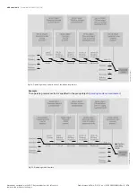
The device counts the number of telegrams sent within the parameterized period. As soon as the maxi-
mum number of sent telegrams is reached, no further telegrams are sent on the bus (ABB i-bus® KNX)
until the end of the period. A new period commences automatically at the end of the previous period.
The telegram counter is reset to zero. Telegrams can be sent again. The group object always sends the
current telegram value.
The first period (break time) is not precisely predefined. The break time can be anywhere between 0 sec-
onds and the parameterized period. The subsequent periods correspond to the parameterized time →
parameter
Example
• Number of telegrams = 20
• Maximum number of telegrams per period = 5
• Period = 5 s
The device immediately sends 5 telegrams. The next 5 telegrams are sent after a maximum of 5 sec-
onds. From this point, a further 5 telegrams are sent via the bus (ABB i-bus® KNX) every 5 seconds.
12.2.19
Valve purge
To prevent the valve from sticking during an extended idle period, the valve is completely opened and
closed one time during the valve purge.
The purge cycle time is restarted after starting the device if automatic valve purge has been activated.
The purging cycle time will be restarted at the end of the actual purging period. The parameterized dura-
tion for the valve purge is included here.
The purging cycle with an active automatic valve purge is reset and restarted if:
• A manual valve purge is triggered.
• The parameterized value (in Reset purge cycle from...) is exceeded. The purging cycle is only restarted
once the parameterized value is reached or dropped below.
After bus voltage recovery and ETS download, the automatic purge cycle is restarted. The time before
bus voltage failure is not considered. If the purge cycle is triggered simultaneously for two valves, purg-
ing will take place one after the other.
12.2.20
Use of 6-way valve
If a 6-way valve is used, both operating modes (
Heating
/
Cooling
) in a 4-pipe system are activated to-
gether on one valve output. Despite the joint activation, both operating modes can be used independent
of each other.
A 6-way valve can be used only if the following prerequisites are met:
• Basic-stage heating is used for a water heating type
• Basic-stage cooling is active
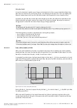
The valve drive for the 6-way valve is connected to valve output A, and the control values for
heating
and
cooling
are issued at this output. The control signal for the drive is given by the two control values and is
divided into a range for
heating
and a range for
cooling
. Between the two ranges there is a dead zone in
which the valve is closed.
Product manual | EN-US | VC/S 4.x.1 | 2CDC508220D0211 Rev. B
190
Note about navigation in the PDF: Key combination 'Alt + left arrow'
jumps to the previous view/page