

This guide provides mechanical and electrical installation information for the
E530 EtherCAT servo drive. For detailed content, please refer to the E530-EC
Servo system user manual (3AXD50001018672 [EN])。
1. Safety instructions
This section contains the safety instructions that must be followed when
installing, operating and maintaining the servo drive. If ignored, it may result in
personal injury or death and damage to the servo drive, motor or drive
equipment. Please read this section carefully before operating the servo drive.
This section lists only the most important safety information for drive
installation, operation and maintenance, For detailed content, please refer to
chapter
Safety
in the E530-EC Servo system user manual (3AXD50001018672
[EN]).
The manual uses these warning symbols:
1.1 Unpacking
1.2 Installation safety instructions
1.3 Wiring safety instructions
1.4 Grounding safety instructions
1.5 Operation safety instructions
1.6 Maintenance safety instructions
2. Product overview
2.1 Drive components
As shown in the figure below, the package of the
drive contains the following components. Make sure
that all the items are present and there are no signs
of damage.
2.2 Drive labels
The drive has two labels:
•
Model information label
in front of the drive.
•
Type designation label
on the left side of the drive.
2.3 Drive interface
Note:
No need to distinguish zero and live wires for AC input ports L1 and L2 of
the drive (F2/F3).
Definition of drive port voltage level:
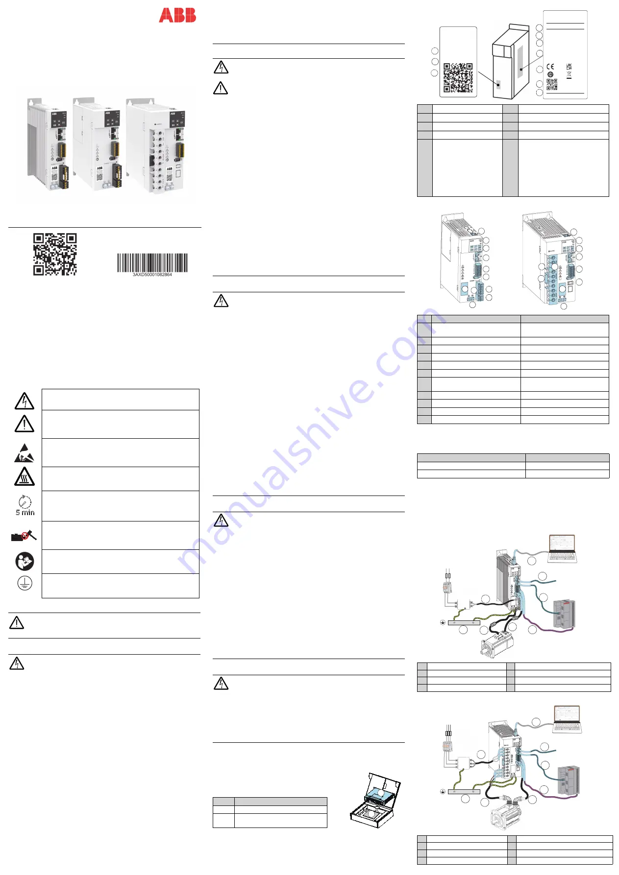
2.4 System structure
This section introduces the connection of the components in the servo drive
system, which helps the users quickly understand the E530 EtherCAT series
servo products. Different frame sizes have different power input and are used
with different types of motors. Taking F2 and F4 as examples, the typical
system connection diagram is shown below.
Frame size F2
Frame size F4
ABB Motion E-catalog
About this document
3AXD50001082864
Rev A EN 2023-12-01
©
2023 ABB All rights reserved.
Electricity warning
tells you about hazards from electricity
which can cause injury or death, or damage to the equipment.
General warning
tells you about conditions, other than those
caused by electricity, which can cause injury or death, or
damage to the equipment.
Electrostatic sensitive devices warning
tells you about the
risk of electrostatic discharge which can cause damage to
the equipment.
Surface high temperature warning
, tells you to pay attention
to the high temperature on the surface of the radiator, there
is a risk of scalding.
Remaining time warning
, displaying the remaining time for
capacitor discharge. After disconnecting the drive power
supply, be sure to wait for five minutes for the capacitor to
discharge. Otherwise, there is a risk of electric shock.
Motor machinery damage warning
tells you about the
dangerous operation like knocking which can damage the
motor.
Refering to the user manual warning
, tells you to read the
user manual and quick installation guide manual before
operating the device.
Grounding warning
, tells you about the protective grounding
(PE conductor terminal). Ensure that the equipment is
securely grounded.
Please check whether the drive type matches the product you ordered.
Make sure the specifications (rated power) of the servo drive and
motor are correctly matched. Ignoring this instruction could result in
personal injury or death or equipment damage.
Warning!
Do not connect the input power to the servo drive during
installation.
•
Move the servo drive carefully to avoid damage.
•
Use lifting equipment to lift the drive. Use the lifting lugs of the drive.
•
Do not tilt the drive. Overturning the drive may cause injury or damage.
•
Please keep the servo drive in the package before installation. After
unpacking, keep away from dust, debris and moisture.
•
Use required personal protective equipment: safety shoes with metal toe
caps, goggles, protective gloves and long sleeves, etc, as some parts have
sharp edges.
•
Do not install the servo drive in the environment of high temperature,
humidity, corrosive gas, flammable and explosive gas, metal dust, oil mist,
water vapor, etc.
•
Do not install the servo drive in a place with continuous vibration or physical
shock, strong electromagnetic interference, or sudden temperature change.
•
Do not fasten the servo drive by riveting or welding.
•
Before starting, vacuum clean the area around the drive to prevent the
cooling fan from sucking dust into the drive.
•
When installing, make sure that debris from drilling and grinding does not
enter the servo drive. Conductive debris inside the servo drive may cause
damage or malfunction of the device.
•
Install the mounting plate as vertical as possible and strong enough to
support the weight of the drive. Metal materials are recommended as the
material for mounting plate. The floor below the installation location should
be made of flame retardant material.
•
The installation site should be well ventilated or have adequate cooling
facilities to remove the heat emitted by the drive.
—
ABB Servo Product
E530-EC servo drive
Quick installation guide
•
Verify that all mounting frames are properly grounded and that contact
surfaces are free of paint.
•
This servo drive does not provide comprehensive mitigation for fire hazards.
It is intended to be installed inside a supplementary enclosure or in a
restricted-access area which provides appropriate protection against spread
of fire.
Warning!
Wiring to the drive must be done by a qualified electrical
engineer. Ignoring the following safety instructions may
cause
personal
injury or death and equipment damage.
Note!
Electrical design and installation must comply with local laws and
regulations. ABB is not responsible for installations that violate local
laws or regulations.
•
Dangerous voltage charges may remain in the drive even after a power
outage, so be sure to wait at least 5 minutes after a power outage to
measure to determine that the device is de-energized before performing any
wiring or inspections.
•
Avoid touching any other live parts in the workplace. Take special
precautions when working near exposed conductors.
•
Make sure that the servo system is safely grounded in accordance with local
regulations to ensure the reliability of the equipment.
•
Do not connect the servo drive to a voltage higher than that marked on the
model label, it can cause damage to internal components.
•
Do not solder exposed wires. Solder will shrink over time, potentially causing
loose connections. Use crimp connections whenever possible.
•
The AC power supply must be fused.
•
The control cable should have sufficient electrical safety distance from the
main circuit cable, or double or reinforced insulation isolation measures
should be provided between the control cable and main circuit cable.
•
After you disconnect power from the drive, always wait 5 minutes to let the
capacitors discharge before you continue.
•
Lock out and tag out after disconnection from power supply, to avoid any
misoperation.
•
E530 EtherCAT servo drive is suitable to be used with residual current
devices of Type B. Other measures for protection in case of direct or indirect
contact, such as separation from the environment by double or reinforced
insulation or isolation from the supply system by a transformer, can also be
applied.
Warning!
Please follow these instructions. Ignoring the following
safety instructions may cause personal injury, increase electromagnetic
interference, and lead to equipment failure. If you are not a qualified
electrical professional, do not perform grounding work.
•
Make sure that the servo drive, motor, and adjacent equipment are
grounded. This is a necessary measure to ensure personal safety. Proper
grounding can also reduce electromagnetic radiation and interference.
•
Make sure that the protective grounding (PE) conductor has sufficient
conductivity. Comply with local regulations.
•
Make sure that the size of the grounding wire meets the requirements of
safety regulations.
•
In a multi servo drive device, connect each one separately to the protective
grounding (PE) of the power supply.
•
When EMC emissions must be minimized, make a 360° grounding at the
cable entries in order to suppress electromagnetic disturbances. In
addition, connect the cable shields to protective earth (PE) in order to meet
safety regulations.
Note:
•
Power cable shields are suitable for equipment grounding conductors only
when adequately sized to meet safety regulations.
•
According to the requirements of standard EN 61800-5-1 (section 4.4.4.3.3),
due to the normal contact current of the servo drive being higher than 3.5
mA AC or 10 mA DC, a fixed protective grounding connection must be used:
- The cross-sectional area of the protective grounding conductor must be
at least 10 mm
2
copper wire or 16 mm
2
aluminum wire, or
- Automatically disconnect the power supply when the protective
grounding conductor is interrupted, or
- Replace with a backup protective grounding conductor with the same
cross-sectional area as the original protective grounding conductor.
•
Leakage current >3.5 mA AC.
Warning!
Before operation, adjust the drive parameters to match the
user-defined parameters of the mechanical system. Mismatched
parameters may cause damage to the servo drive, motor or mechanical
system.
•
Adjust the limit value (speed, current, etc.) of the servo drive, and make sure
that the motor and all driven equipment can run within the limit range.
•
Be careful with hot surfaces. During use, the surfaces of servo system
components (such as reactors or braking resistors) can become very hot and
remain hot for a period of time after the power is disconnected. Braking
resistors may generate enough heat to ignite flammable materials. To avoid
fire hazard, keep all flammable materials and flammable substances away
from the braking resistor.
•
Make sure that the safety circuits (eg emergency stop) connected to the
servo drive are verified.
•
The servo drive is allowed to power on up to 5 times every 10 minutes. Too
frequent power-ups can damage the DC capacitor charging circuit.
•
Before using the automatic fault reset or automatic restart function of the
servo drive, make sure that no dangerous situation occurs. After a fault or
power interruption, the servo drive automatically resets and continues to run
through these functions. If these functions are used, they must be clearly
marked on the equipment as specified in IEC/EN 61800-5-1, clause 6.5.3, eg
"This equipment will start up automatically".
Warning!
Maintenance and inspection of the drive should only be
performed by a qualified electrical engineer. Do not touch any internal
or external parts of the servo drive and motor, as doing so may result in
electric shock.
•
The fan and other components of the servo drive are replaced and
maintained by ABB or an authorized service center, Users are not allowed to
disassemble them.
•
Servo drives are not field repairable. Do not repair a malfunctioning servo
drive. If the servo drive fails, please contact your local ABB office or
authorized service center.
No.
Description
1
Servo drive
2
E530 EtherCAT variant servo drive
quick installation guide(ZH & EN)
ABB
1
2
1
Drive type
6
QR code (Production serial number)
2
Manufacturer information
7
Drive type
3
Degree of protection
8
Serial number
4
Nominal ratings
9
QR code (ABB servo web site)
5
Certification markings
10
S/N: Serial number of format
MYYWWXXXXX, where
M: Manufacturer designation
YY: Year of manufacture: 20, 21, 22,
…for year 2020, 2021, 2022…
WW: Week of manufacture: 01,02,03,
…for week 1, week 2, week 3...
XXXXX: Running item number that
starts each week from 00001.
No.
F2,F3
F4
1
Commissioning software
connection port (RJ 45)
Commissioning software
connection port (RJ 45)
2
Five digit seven segment LED
Five digit seven segment LED
3
Display operation buttons
Display operation buttons
4
EtherCAT communication interface EtherCAT communication interface
5
Control signal connector
Control signal connector
6
Encoder connector
Encoder connector
7
Input power and brake resistor
connection terminals
Input power, motor power and
brake resistor connection terminals
8
Motor power connection terminals Model information label
9
Model information label
Short-circuit connector
10 Short-circuit connector
Baffe
11 Grounding screws
Grounding screws
Drive port
DVC level
CN1/CN2/CN3
DVC As
L1/L2/L3/P/C/R/U/V/W
DVC C
1
Power cable, 1-phase
5
Communication cable (RJ45)
2
Motor cables
6
System grounding busbar
3 Encoder cable (1394 connector) 7 EtherCAT communication cable input
4 Control cable (16-pin connector) 8 EtherCAT communication cable output
1 Power cable, 1-phase or 3-phase 5
Communication cable (RJ45)
2
Motor cables
6
System grounding busbar
3 Encoder cable (1394 connector) 7 EtherCAT communication cable input
4 Control cable (16-pin connector) 8 EtherCAT communication cable output
7
8
9
5
1
2
3
4
6
10
E530-EC0S-0KW4-1
220 VAC, 0.40 kW, EC
S/N W2
!
12345
ABB Beijing Drive Systems Co.,Ltd.
No.1, Block D, A-10 Jiuxianqiao Beilu,
Chaoyang District, Beijing, P.R. China
Made in China
S/N W222312345
Output
Input
3P 0~U1
U2
1P 200~240VAC
U1
2.90 A
I2
4.7 A
I1
0~500Hz
f2
50/60Hz
f1
0.40 kW
Pn
E530-EC0S-0KW4-1
5 kA
Icc
Natural cooling
C
HW
IP20 Open type
ABB Oy
1
3
4
5
6
7
8
9
1
2
3
4
5
6
7
9
10
F2、F3
F4
2
11
10
11
8
Externl PC
(Install Servo Composer)
PLC/controller
220V AC power
Breaker
Fuse
Filter
1
2
3
4
5
6
8
Connect to the
next drive or
PLC to form
redundant
connections
PE
7
External PC
(Install Servo Composer)
PLC/controller
220V AC power
Breaker
Fuse
1
2
3
4
5
6
7
Connect to
the next drive
or PLC to form
redundant
connections
PE
8
Filter