


Modifications reserved
Page 12/79
3.2
Main elements description
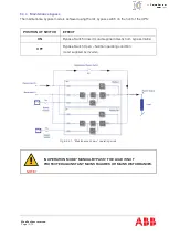
3.2.1
Single line diagram
Fig 3.2.1-1: Single line diagram
3.2.2
Functional description
Section
Component
Functional Description
Main input terminals
1L1
Rectifier mains terminal, Phase 1
Provides a connection between the utility supply
and the rectifier input
1L2
Rectifier mains terminal, Phase 2
1L3
Rectifier mains terminal, Phase 3
1N
Neutral terminal
PE
Earth terminal
Bypass input terminals
2L1
Bypass Main Input Terminal, Phase 1
Provides a connection between the bypass
supply and UPS bypass input
2L2
Bypass Main Input Terminal, Phase 2
2L3
Bypass Main Input Terminal, Phase 3
2N
Neutral terminal
System output terminals
3L1
System Output Terminal, Phase 1
Provides a connection between the UPS system
and the load
3L2
System Output Terminal, Phase 2
3L3
System Output Terminal, Phase 3
3N
Neutral terminal
PE
Earth terminal
Summary of Contents for DPA UPScale ST40
Page 1: ... Copyright 2017 ABB All rights reserved User Manual DPA UPScaleTM ST S2 10 200 kW ...
Page 76: ...Modifications reserved Page 76 79 10 Attachments 10 1 Technical data sheet ...
Page 78: ......
Page 79: ... Copyright 2017 ABB All rights reserved Technical data sheet DPA UPScaleTM ST S2 10 200 kW ...
Page 104: ......
Page 105: ... Copyright 2017 ABB All rights reserved Technical data sheet DPA UPScaleTM ST S2 10 200 kW ...


