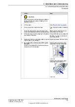
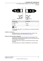
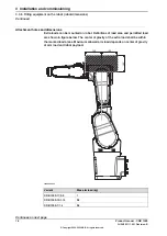
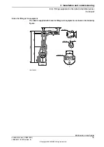
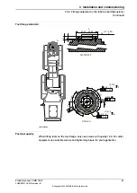


Preparing the adapter
The lead-through device is mounted to the device base and then to the robot tool
flange through an adapter. Customers can use an L-shape adapter offered by ABB
(option 3314-1) or design adapters according to actual requirements. During adapter
design, hole dimensions on the device base and robot tool flange shall be
considered.
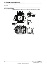
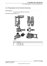
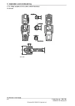
The following figure illustrates the hole dimensions on lead-through device base.
8
10,1
20
68,8
16,9
39,4
26,4
19,5 ±0,15
19,5 ±0,15
R3
R29,75
4 x M4 THRU
25 ±0,1
30°
2 x
4.5 THRU
8
4.4
52
36
xx2200000767
For the hole dimensions on robot tool flange, see
Tool flange standard on page 81
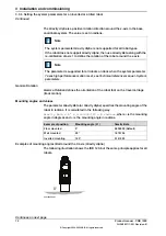
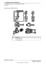
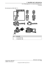
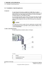
Required spare parts
Note
The spare part numbers that are listed in the table can be out of date. See the
latest spare parts of the CRB 1300 via myABB Business Portal,
.
Note
Article number
Spare part
3HAC082590-001
Lead-through device with buttons
3HAC082591-001
Lead-through device base
3HAC085155-001
Cabling M8-M12, 700 mm (for lead-
through device)
3HAC077020-001
Ethernet cable M12- RJ45, 7m (for
lead-through device)
Continues on next page
Product manual - CRB 1300
83
3HAC083111-001 Revision: B
© Copyright 2022-2023 ABB. All rights reserved.
3 Installation and commissioning
3.3.7 Installation of lead-through device
Continued
Summary of Contents for CRB 1300
Page 1: ...ROBOTICS Product manual CRB 1300 ...
Page 50: ...This page is intentionally left blank ...
Page 662: ...This page is intentionally left blank ...
Page 690: ...This page is intentionally left blank ...
Page 704: ...This page is intentionally left blank ...
Page 720: ...This page is intentionally left blank ...
Page 725: ......