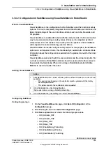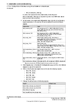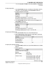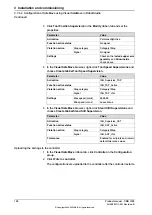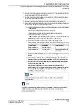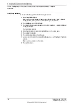
Configuring the laser scanner
Protection fields
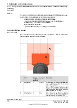
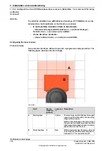
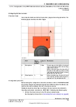
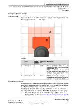
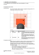
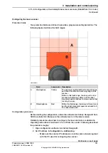
Two protection fields are defined to provide a progressive safety protection. The
following figure illustrates the field ranges.
xx2200000301
Description
Lamp col-
or
Device
mapping
(default)
Field
The warning area field defines the largest
range, but it shall be within the scanning
range of the scanner.
Yellow
1
WarningArea
A
Within in this field range, the lamp unit on
the process hub lights up yellow, and the
robot movement speed reduces to a lower
speed that is set by the user.
Within this field range, the lamp unit turns
to red and the robot movement speed is
reduced to 0. The robot stands still.
Red
0
ProtectingArea
B
Configuration procedure
Before starting the configuration, obtain the
microScan 3 Core - PROFINET GSDML
file and the software tool
Safety Designer®
from SICK's website first. Make sure
both the file and the software tool are in the latest versions.
Detailed procedures about how to configure the laser scanner are detailed in
Operating instructions microScan3 - PROFINET
. Following described roughly:
1 Connect the laser scanner to the PC using a network cable.
See the physical connection in
Connecting the laser scanner(s) on page 89
Continues on next page
Product manual - CRB 1300
139
3HAC083111-001 Revision: B
© Copyright 2022-2023 ABB. All rights reserved.
3 Installation and commissioning
3.7.5.3 Configuration of one PROFIsafe-based laser scanner (RobotWare 7.10 or later and OmniCore
acting as Master)
Continued
Summary of Contents for CRB 1300
Page 1: ...ROBOTICS Product manual CRB 1300 ...
Page 50: ...This page is intentionally left blank ...
Page 662: ...This page is intentionally left blank ...
Page 690: ...This page is intentionally left blank ...
Page 704: ...This page is intentionally left blank ...
Page 720: ...This page is intentionally left blank ...
Page 725: ......

